ConventionalMemories wrote on 2020-12-21, 16:03:Wow, that's some amazing work. Thank you for reverse engineering that board for us all.
What where the most common components t […]
Show full quote
FuST wrote on 2020-12-20, 14:43:I have updated the schematic slightly as I noticed some errors while fixing the first machine's PSU board, V1.1 is included as a […]
Show full quote
I have updated the schematic slightly as I noticed some errors while fixing the first machine's PSU board, V1.1 is included as an attachment.
I am documenting the entire process and will release it to my YouTube channel when I'm done.
I also made a vieo describing how the PSU board actually works which I will release somewhere in the following weeks.
T1600 PSU Schematic (v1.1).pdf
Wow, that's some amazing work. Thank you for reverse engineering that board for us all.
What where the most common components to fail in your experience? Might help me repairing my two T1600's
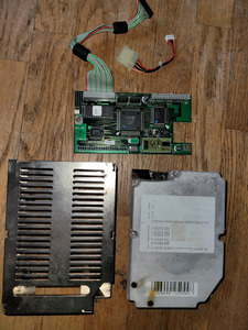
You mentioned looking for an XT-IDE solution, I have a Compact Flash adapter up for sale that fits in the expansion slot with XTIDE rom on board. It can also be configured to control the internal IDE controller. https://www.benl.ebay.be/itm/264877993192
If you're interested I'd be happy to send you one for free as a thank you for all the hard work.
Now next up the T1200 and T3100sx. 😉
(They appear to have similar power board issues, recapped, no signs of corrosion, check all vias, no sign of life. Power LED blinks red when trying to power on)
Thank you very much!
First let me answer your question. This will be a bit lengthy as I'll explain what I found wrong with my boards.
The most common components are obviously the capacitors. This is, as you probably already know, a problem for all Toshiba laptops from the late 80's/early 90's. My T1200XE and all 3 of my T1000LE's suffered the exact same problems.
In fact, I would go as far as to say that when you get a late 80's/early 90's Toshiba you shouldn't even plug it in. Just take it apart immediatly and replace the caps to prevent more serious damage.
One thing to note here is that these caps are part of a switchmode powersupply (buck, boost and buck/boost converters) so replace them with name brand, high-temp, low-esr ones (I used Panasonic and Würth).
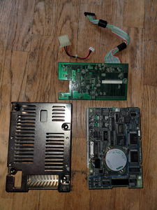
The T1600/40's PSU board actually had nothing else wrong with it component-wise, it just had two broken traces.
The T1600's PSU board had a lot more wrong with it.
Before I got it Q29 was already destroyed, as well as C38.
There was a trace broken between the negative side of C4 and the trace going off to PJ2 (main connector).
There were also traces broken between R135 and PJ3 pin 1 (R135 is part of a voltage devider to sense the battery voltage) and between R137 and a via hole leading to IC13 (R137 is a pullup resistor).
I started desoldering the power MOSFETS so I could put them into my component tester and found Q3, Q4 and Q5 to be defective.
Mosfet #2 of IC5 (pin 3 input, pin 18 output) was damaged, it wouldn't turn off fully in a test setup.
Finally, the diode I mentioned in my last post.
A lot of other components died in the testing process, partly because of my stupidity in not verifying my work properly and not powering off the board when testing with my multimeter.
The irreplaceable parts (the IC12 & IC13 MCUs and the IC3 gate array) are pretty well protected, anything else is still somewhat available, if you are willing to order stuff from DigiKey/Mouser and AliExpress.
The only thing I can't find besides one webshop in Italy is the ceramic resonator for IC12 (X2) but unfortunately they require a minimum order of €30,- and the component is only €0,50 so one of my T1000LE's has to do without one for now.
As I said in my previous post, I really suggest getting a storage oscilloscope. It will allow you to visualize what the board is doing and if all the voltage rails come online.
It also comes in handy when trying to see if the MOSFETS and the transistors driving them are actually switching properly, things like a broken diode or transistor will show up way easier than trying to measure everything in-circuit.
I'd be happy to take some screenshots on my scope at certain points on the board to show what it should look like.
In fact, I might even just do that and add it to the schematic PDF, along with some text explaining how the thing works.
Pfeeewww, that's a wall of text isn't it?
Now, on the subject of a XT-IDE.
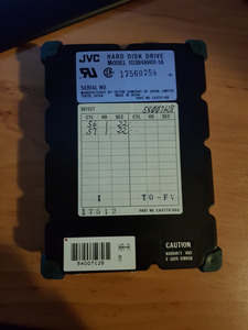
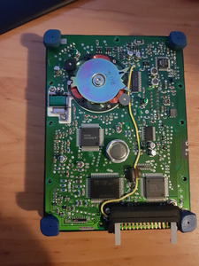
I actually noticed your boards a while back when you posted about them on Reddit and was considering buying one for the T1600/40. The JVC harddrive is kind of an odd beast and chances of repairing it are slim to none.
You offering to send me one for free has me at a bit of a loss for words to be honest, that is very generous and kind. It's something I never expected when I uploaded the schematics so they might be of use to other people in the community.
I'm definitely interested in one and really appreciate the offer. Could you send me a PM so we can talk about shipping, etc?
Having typed all this, if anyone has any questions regarding these PSU boards, I'm happy to help out where I can.
This was a challenging, fiddly, time-consuming and at some times very frustrating thing to do but man is it satisfying when it finally works.
After all, it's just electronics. Anything is fixable with the right tools, knowledge and a lot of spare time 😜