VOGONS


The 286 Laptop Restoration Thread

Topic actions

Reply 60 of 75, by twospruces

User metadata
Rank Newbie
Rank
Newbie
FuST wrote on 2023-06-16, 20:26:
The first T1000XE wasn't that hard to fix, replacing a couple of capacitors and some minor PCB repair did the trick. I started w […]
Show full quote

The first T1000XE wasn't that hard to fix, replacing a couple of capacitors and some minor PCB repair did the trick.
I started work on the second machine I got but haven't got around to finishing it, real life kind of got in the way.

I did start work on a T1000 which confirmed my thoughts on all the T-series machines having a similar architecture for the PSU section.

If the PCB looks good you're probably going to be okay with just replacing the caps in the buck/boost converters (i.e. the larger ones). The switching MOSFETs/transistors can take quite a beating on these.

Well, I have replaced all the electrolytics. Many were leaking. The pcb looks great though.

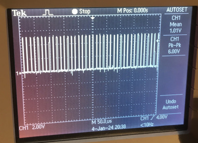
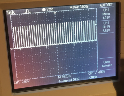
I am actively scoping the various rails to try and see why it won't fully power up.

What I observe is that, on pressing power button, all the converters activate but after a second or 2 the controller shuts the supply down via logic on pin 33 of the processor.

I can see the 6xAA kluged battery pack struggling under the load which I think is more than an Amp because the AA cells are <1V during power up. With full
Nimh Batts that's a lot of current.

All the major transistors seem ok.
I found a damaged diode that appears to stll work...curious.

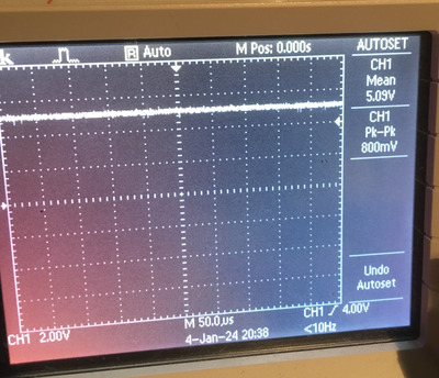
I feel like the 5V rail is where the current is going. I have removed all 5 soldered jumpers which I think isolates the supply from the board. Same failure. So that makes me suspect the 5v converter is somehow Sinking a lot of current . I don't have a good way of measuring the transient current through the psu to really know though.

So my thesis is that the 5v converter struggles and pulls a lot of current, which the controller senses, and them shuts down.

Tough slogging. Your T1600 schematic is helpful as is your repair guide.

Reply 61 of 75, by FuST

User metadata
Rank Newbie
Rank
Newbie

The controller can't sense current draw directly, it doesn't have the circuitry to do that.
A possibility is that one of the rails gets loaded down a lot which causes the voltage to not reach the appropriate level in time causing the controller to shut things down.
A 4-channel scope is handy in these situations as you can monitor all voltage rails simultaneously.
The damaged diode seems suspect to me, the switching regulators use shottky diodes because of their low forward resistance. I'd advise to check (out of circuit) that they are within spec and are actually still diodes.
Scoping both sides of the diodes when the PSU is running (or trying to) should also validate this: one side should show the switching of the transistor and the other should be smooth which is a nice property of how buck/boost converters work

IIRC the problem with my second T1000XE is that it doesn't power up when the LCD is connected, which is where I was stuck at at the time.
Disconnecting the LCD and removing all the jumper links that connect the PSU section to the rest of the board is how I started troubleshooting, it isolates any other problems.

Also note that the battery pack must (for some reason unbeknownst to me) be present on the 'XE and have at least some charge in it so it is detected by the controller IC.
I've replaced the cells in one of my T1000LE/XE batterypacks with a couple of NiCd AA cells from Amazon, those work like a charm and don't require any changes to the charging circuitry.

Blog | YouTube

Reply 62 of 75, by twospruces

User metadata
Rank Newbie
Rank
Newbie

Gut check on output voltages..

W504 W504 = 5V ie VCC
W501 = 12V
W502 = -9v

VEE for LCD =??? What's this rail supposed to be? Probably not -25v I would guess. That's what I have.

Edit. Vee for LCD is 22V. So that's good. I found a table of supply ratings for T12oo in the maintenance manual. Very helpful. Lists out what subsystems get what power.

Reply 63 of 75, by twospruces

User metadata
Rank Newbie
Rank
Newbie

Well thank you for your hard work on that T1600 schematic. T1000XE is close enough for that doc to be quite helpful. I got my machine working today. Quite a bit of effort to find the blown parts. For me, I had a blown LM358 that provided sense signals to the controller. Also I had a blown transceiver which was loading -9V way too much. Also some small diodes were blown. Lots of time to find the issues!

Reply 64 of 75, by FuST

User metadata
Rank Newbie
Rank
Newbie

That's good to hear, glad the T1600 schematic helped.
It's unfortunately not uncommon for more parts (like diodes and the comparator) to fail as people try to power the machine up without replacing the caps. It can cause some pretty large voltage spikes when they're not doing their job correctly and it's a nightmare to track down without knowing how it all works together.

Anyway, glad another T1000XE was saved from becoming scrap!

Blog | YouTube

Reply 65 of 75, by sebulba

User metadata
Rank Newbie
Rank
Newbie

Hey, reviving this thread and I'm reviving a toshiba 286 laptop as well

In my case it's a Toshiba T2000/40 -- which seem to be rare and information about it is hard to find.

I have two issues
1) I've got the freaking PSU problems "red blink" everyone else is having with this generation of laptop, I won't go into that now.
2) my screen behaves in a weird way

ced_2023-08-08@12h18_IMG_1442.JPG
Filename
ced_2023-08-08@12h18_IMG_1442.JPG
File size
1.81 MiB
Views
649 views
File license
Fair use/fair dealing exception
ced_2023-08-08@12h11_IMG_1441.JPG
Filename
ced_2023-08-08@12h11_IMG_1441.JPG
File size
1.37 MiB
Views
649 views
File license
Public domain

As you can see, it's perfectly split in two. It does not seem to be a backlight problem as the separation is pixel perfect
In (reverse) text mode, you can see the white is just less white in the bottom half of the screen

In WIndows 3.1 you can see that actually colors (out of the 16 gray levels) are actually missing in the second half. Bottom of the window's corners are missing the white outline, pixels are also missing here and there.
I tried lowering the number of colors in the bios (16 or 😎 and the result is the same

Did anyone ever see this problem, I'm really open to suggestions.
Is it in the screen ? In the video RAM ? In a cable ?

It's really like a bit or two is/are missing out of the bottom half of the screen.

Any advice is greatly appreciated

Reply 66 of 75, by BitWrangler

User metadata
Rank l33t++
Rank
l33t++

I've got a similar problem on an AST Premium Exec 386 with mono screen... I've tried everything up to dismantling the LCD module, sometimes pressure on the edge of that seems to cure it temporarily. So I am assuming there are solder or other problems inside. I have not gone into it yet, due to having no info on how "reversible" the disassembly is. Probably the easy fix is to take model info off the panel assembly and attempt to get a good deal on a replacement.

Unicorn herding operations are proceeding, but all the totes of hens teeth and barrels of rocking horse poop give them plenty of hiding spots.

Reply 67 of 75, by FuST

User metadata
Rank Newbie
Rank
Newbie

Could be a number of things, really.
What springs to mind:
Dodgy capacitors on the LCD module
Cold (cracked) solder joints
Bad contact on the LCD zebra strip (I don't know if this LCD has those and I'm not sure that wpuld cause this type of fault)
Bad LCD driver ICs on the LCD module
Bad video cable
Bad video RAM / display driver circuitry.

Does this model have an RGB (CGA/EGA style) or composite video connector so you can rule out the video circuitry on the mainboard using an external monitor?

Blog | YouTube

Reply 68 of 75, by perezx

User metadata
Rank Newbie
Rank
Newbie

Okay, guys... next one 😀
I also got the T1600 with non-working PSU. "Troubleshooting manual" describes the procedure of PSU diagnostics as the batteries should not be connected. However, on the 1st page of this thread it is clearly indicated that they should.
So the question is: do I have to repair batteries (main right and left and ram-backup-battery) and connect them prior to trying start the PSU ? I have already checked the board, FETs, +5V and clock on both controllers - and got nothing. As soon as I press start button red LED starts blinking whithout any attempt to start PWM converters.

Reply 69 of 75, by FuST

User metadata
Rank Newbie
Rank
Newbie

Batteries are not required for the T1600 PSU board to operate. The rest of the computer isn't even required, it will work stand-alone (i.e. only connected to the 12V DC brick).

Is there no PWM on the MOSFET gates at all? If it attempts to start but fails to reach the proper voltages in time there should at least be some PWM activity for a short (couple tens to hundreds of ms) while.
If there's no PWM at all I'd check if the internal 18V main bus comes up as this drives all the other converters.

Blog | YouTube

Reply 70 of 75, by perezx

User metadata
Rank Newbie
Rank
Newbie

Thanks a lot! I am reading through your notes and diagrams for last 2 weeks 😀
Well, "just on the table" the PSU behaves a bit erratically. It does not start and does not even try to start 18W buck-boost when I press the button. I attached LEDs to 5VA, 5VB and 18V rails - well, right after switch on 5VA and 5VB are on, couple seconds after that moment 5VB goes down. Push the button and 5VB goes up and immediately red light starts blinking. No sign of flash on 18V and no clicking sound, just silence. Actually, no PWM on IC13 outputs.
However, just at powerup (+12 from mains) PSU might (or might not) produce a couple of clicks and very short flashes on 18V rail meaning it tries to launch main converter. Then it reverts to usual state: steady red, +5VA and no luck when button pressed.

Reply 71 of 75, by FuST

User metadata
Rank Newbie
Rank
Newbie

Had to have a bit of a think about this.
The behaviour you're seeing with the 5VA and 5VB bus makes sense. I had to wait a couple of seconds after 5VB went off before attempting another powerup.
A clicking sound would suggest that a capacitor or inductor is shorting, the PCB should be completely silent when running.

Let's start at the 18V bus to make sure it actually comes up to the full 18V.
The 18V bus is enabled by Q14.
The converter itself is controlled by IC13, the signal is buffered by IC5 and then sent to Q29. It further consists of inductor L6, shottky diode "7" and C7.
I'd start by checking these components (Q14, Q29, L6, "7" and C7) are good.
A bit further down the signal path:
The 18V zener diode "9" controls Q27 which can in turn pull the PWM signal to Q29 to ground.
This works as a failsafe, when the 18V rail rises too high the PWM is shut off.
C6 is a tank/smoothing capacitor.

The voltage on the 18V bus is sensed through a voltage divider formed by R57 & R58 and fed to IC13 pin 2 through current-limiting resistor R96.
Check continuity on those current paths.

Do you have access to a 'scope? It's pretty much required to do further troubleshooting.
Even one of those cheap Chinese pocket-type ones can be helpful as the signals that need to be checked are way too fast/short for LEDs.
For example: The 18V bus should come up within a couple of 100 _micro_seconds. Too slow and the processor will give up.

Blog | YouTube

Reply 72 of 75, by perezx

User metadata
Rank Newbie
Rank
Newbie

Thanks a lot for your support!
By "clicking sound" I mean normal sound of working inductors, especially they are switching on. They arent completely silent 😀
I will re-check the sequence you suggested, but as far as I remember, PWM do not appear at all on pin34 of IC13.
My scope is Tektronix TDS1012, old, but seems to be working good enough.

One more question: can you measure signals on pins 1-3 of IC12, coming from what you named "current sensing"? In Multisim model I got they should be around 0 volts during normal work. In reality I got approx. +1.1V there.

Reply 73 of 75, by FuST

User metadata
Rank Newbie
Rank
Newbie

My PSUs don't make any sound when running. At least nothing I'm able to hear which is generally anything below ~18KHz.
When the board is first switched on there is a bit of sound from the inductors physically deforming a bit under the magnetic field, I guess that could qualify as a "clicking sound".

That Tektronix 'scope should be more than enough.
When trying to see if there is any PWM signals make sure to set it to single-shot trigger mode.

The voltage on those pins seems about right.
This is one of the problems with circuit simulators: they assume perfect components, zero-resistance wires, etc.
Pin 1 measures the current consumed by the entire board (and entire PC when installed) which can never be zero.
Because the MPU uses a 0 - 5V reference voltage it has to be a positive value.

I've checked on one of my T1600's, I get between 0.8V and 1.2V on pin 1, and 1V on pin 2 and 3 when powered off.
Powered on pin 1 hovers between 1.5V and ~2V, pins 2 and 3 are unchanged.
This makes sense as the board is running, thus consuming more power which is reflected by the higher voltage on pin 1.
Pin 2&3 are the same as no batteries are connected.

Blog | YouTube

Reply 74 of 75, by perezx

User metadata
Rank Newbie
Rank
Newbie

Oh, thank you so much and, of course, Merry Christmas and Happy New Year!
I was quite busy with a bit bigger machine (particle accelerator, which doesnt want to work too) but never forgot about the laptop's PSU.
Now I spent couple hours looking for some patterns in how does it start.
Well, I still do not understand for what reason it tries (or not - 50/50 chance) to produce PWM at the very power-on (before ptressing the button), but at least in some cases the signal at pin34 IC 13 looks like pic.1 Good enough?
Then in couple milliseconds it comes to DC 5V and stays so for 3-4 seconds (pic.2 ) until IC12 removes 5v_B from IC13. If the button pressed within these seconds (while 5V_B still high) - no PWM and LED starts blinking.
If the button is pressed after 5v_B is down, then 100% chance of getting one more attempt to start 18V PWM as on pic.3.
Looks like normal logic for CPU? I guess I should trace this PWM signal further thru the gate and FETs (however, I've checked all the FETs out of board)

Attachments

  • IMG_9842.jpg
    Filename
    IMG_9842.jpg
    File size
    792.53 KiB
    Views
    212 views
    File comment
    Pic. 3. PWM re-attempt after IC13 was powered down by IC12
    File license
    Fair use/fair dealing exception
  • IMG_9841.jpg
    Filename
    IMG_9841.jpg
    File size
    1.02 MiB
    Views
    212 views
    File comment
    Pic. 2. PWM cancelled
    File license
    Fair use/fair dealing exception
  • IMG_9840.jpg
    Filename
    IMG_9840.jpg
    File size
    955.15 KiB
    Views
    212 views
    File comment
    Pic. 1. Power just plugged in, IC 13 produces PWM
    File license
    Fair use/fair dealing exception

Reply 75 of 75, by FuST

User metadata
Rank Newbie
Rank
Newbie

Those PWM signals look normal to me.
The blinking LED when trying to re-power the board is something I encountered as well. You have to wait for the 5V_B rail to drop below TTL logic high (around 2V) but preferably 0V.
Makes testing and debugging a bit tedious as the capacitance on that rail means it can take up to 5 seconds before another attempt can be done.

Next check I would do is if the PWM makes it to Q29 and if any 18V comes up and regulates properly.
If so it's time to start checking the other PWM driver pins on the ICs, check the MOSFET gates, etc.

Blog | YouTube