VOGONS


First post, by Malvineous

User metadata
Rank Oldbie
Rank
Oldbie

Hi all,

I have just succeeded in getting the XTIDE ROM working with my repaired 286, but there was a bit of a trick to getting the ROM chip into the machine so I thought I'd do a writeup of the process in case anyone has a similar issue one day.

I hadn't realised that most if not all ISA boot ROM sockets are 28-pin, while most EEPROMs (certainly the ones you can still buy new today) are 32-pin. This makes it seemingly impossible to buy a new EEPROM and put it in an old ISA network card to get the XTIDE BIOS going - the only option would be a Lo-tech ROM board, which has a 32-pin EEPROM socket.

Well as it turns out, the sockets are largely pin compatible, and it only takes a minor change to be able to connect a 32-pin EEPROM to a 28-pin socket. I have written a detailed guide about how this works and how to build a cheap adapter to do this in case anyone is interested. In short, you connect a couple of the pins together on a 32-pin ROM socket, then use it as an adapter between the 28-pin boot ROM socket and the 32-pin flash chip.

This piggy-back arrangement looks like this:

thumb.nic.piggyback_eeprom.side.jpg

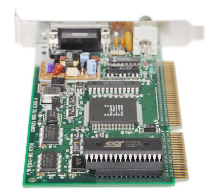
And when it's plugged into my 286, it picks up the ROM without any issues:

xtide.286.boot.jpg

Since I plan to have a network card in my 286 anyway, sticking the XTIDE ROM in there will save me a slot too!

Reply 1 of 4, by PCBONEZ

User metadata
Rank Oldbie
Rank
Oldbie

I just wanted to say good project and nice work.
I have saved your article for future reference.
Thank you.
.

GRUMPY OLD FART - On Hiatus, sort'a
Mann-Made Global Warming. - We should be more concerned about the Intellectual Climate.
You can teach a man to fish and feed him for life, but if he can't handle sushi you must also teach him to cook.

Reply 3 of 4, by devius

User metadata
Rank Oldbie
Rank
Oldbie

I was trying to use this method and eventually got it to work, but the EEPROM I was using was different from the one mentioned in the link so wanted to add some more details in case it helps anyone in the future.

My device was a AT29C010 which is 128KB, as opposed to 512KB as in the article. Since it's mentioned that by wiring A17 to +5V will cause the chip to only be able to access the upper 128KB of memory and my chip is only 128KB anyway I figured I'd be fine and didn't need to worry too much with how I was preparing the image, so I just used the ide_at.bin file as base, and after using xtidecfg.com to configure it got a 8KB file which I just concatenated with an extra 120KB of zeros, assuming that if the ROM image was at the beginning I wouldn't have any issues. I was wrong. Even with a 128KB chip and only being able to access this capacity with the adapter the PC would not detect the boot ROM code. In fact, using the network card's config utility it never detected the ROM chip at all.

What I did was to repeat the base ROM image to fill the 128KB instead of using just zeros, and this allowed the PC to detect and boot using XT-IDE.

I'm not sure why this is needed, but it seems that either the chip or the Ethernet card I'm using doesn't start reading from the start of the ROM, but this is just speculation.

Reply 4 of 4, by stamasd

User metadata
Rank l33t
Rank
l33t

For XTIDE you can use the still widely available W28C512, 64kB in 28-pin package. They are easy to find and cheap. No tricks needed. https://media.digikey.com/pdf/Data%20Sheets/W … DFs/W27C512.pdf

I/O, I/O,
It's off to disk I go,
With a bit and a byte
And a read and a write,
I/O, I/O