VOGONS


First post, by angelripper

User metadata
Rank Newbie
Rank
Newbie

Hi guys,

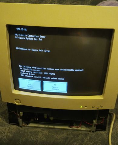
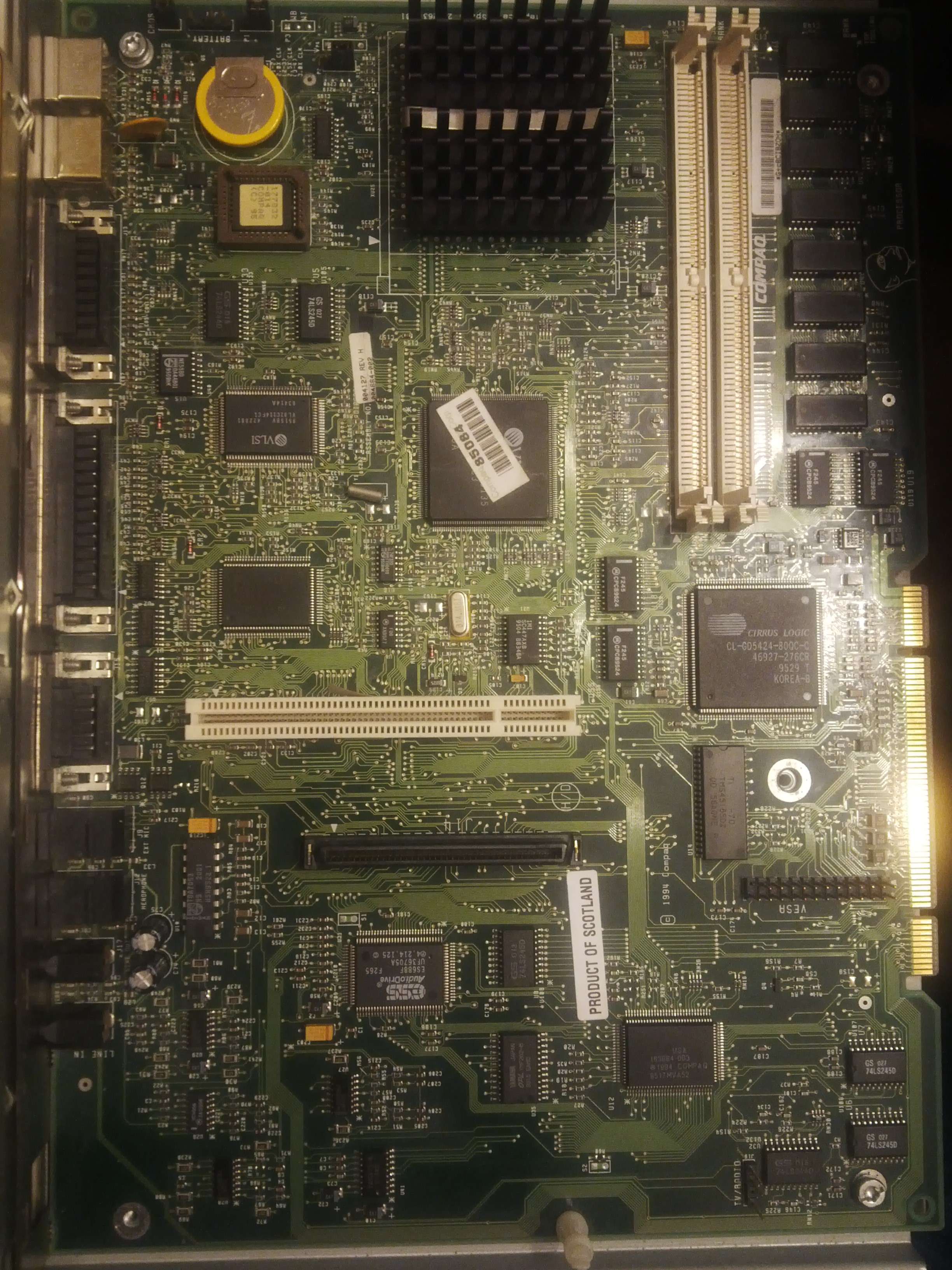
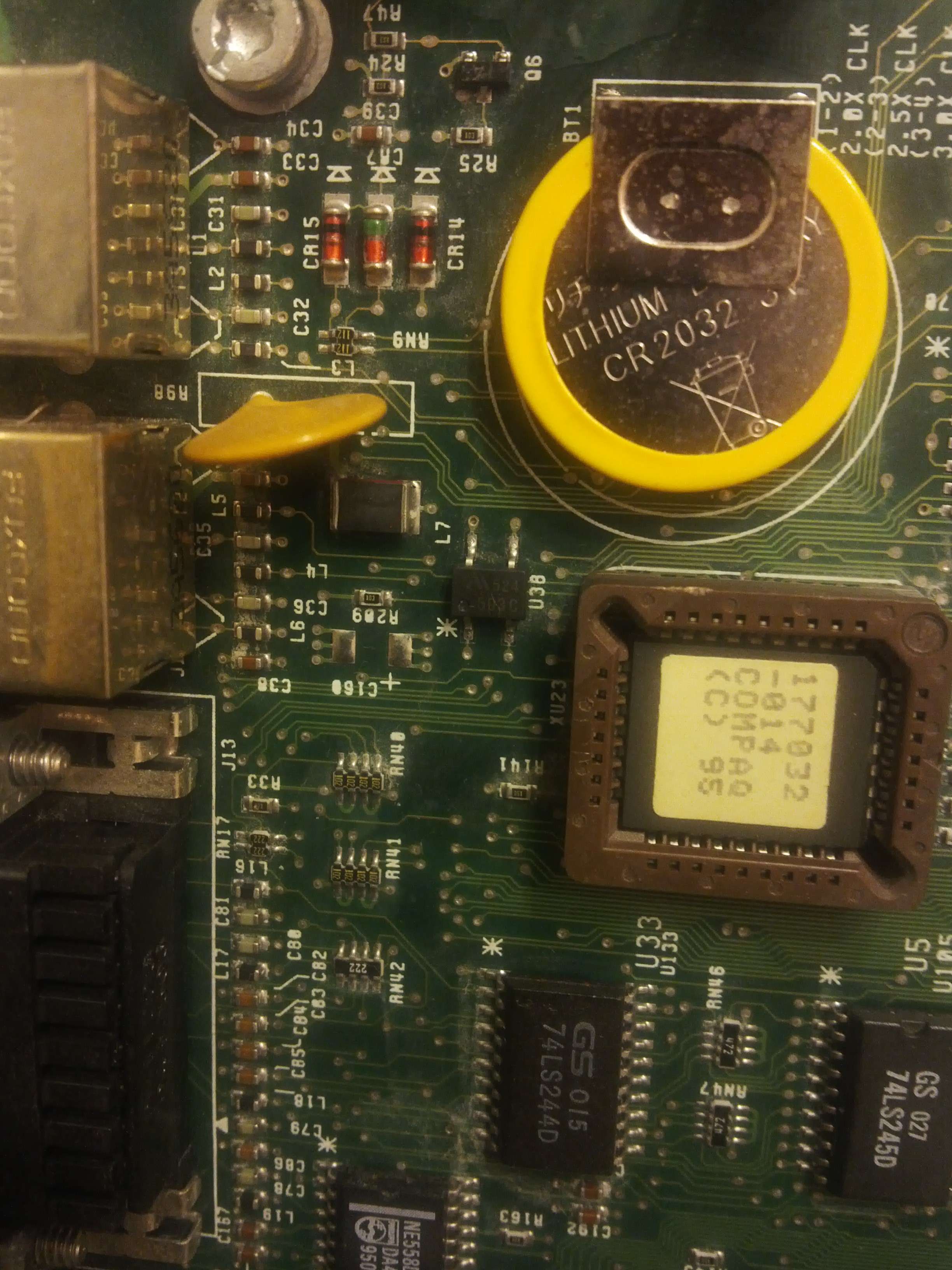
I really need your help. Here's the story - recently I felt in love with those All-in-one PCs. It all started with a Compaq Prolinea Net 1/33s and it was so nice and sexy, that I just couldn't resist buying another one. This time it was Presario CDS 524. The seller has described it as non working and posted a photo with an error message saying "102 - System board failure". Sounds pretty serious, huh? Right, but there was another photo depicting the system board clearly lacking the CMOS battery. Google said, that this error can happen when the battery is flat. I decided to give it a try, and here I am 😀 I soldered a replacement battery, disconnected the CMOS jumper, but still without any success. I also disconnected all drives, removed two SIMMs from the Motherboard, reseated the BIOS chip and cleaned the edge connector, but I'm running out of ideas.

I assume that both CPU and RAM must be OK since there's reaction from BIOS, but I'm really not familiar with Compaq hardware so I can be wrong as well. I have heard that some models (including mine) was equipped with a kind of "hybrid" BIOS, where some diagnostic software was invoked from a hidden partition on a hard drive. My HDD seems to be working and there's a small 3MB OEM type partition before the "big" one. But I also read that it's not obligatory to boot the OS.

Any troubleshooting tips? Any help will be appreciated.

Last edited by angelripper on 2015-12-15, 21:18. Edited 1 time in total.

Reply 1 of 19, by Dropcik

User metadata
Rank Newbie
Rank
Newbie

Usually what I do is take out the motherboard and I clean it and check it over for any signs of burnt components or scratched traces. Front and back. Check all connectors bent pins too. Check the voltage on the power supply as well. It is a bit of work for something that might not be there, but its another variable we can eliminate.

Ayy LMAO

Reply 2 of 19, by angelripper

User metadata
Rank Newbie
Rank
Newbie

The motherboard looks good and clean, there have been two big flux residues, one on the WT/WB (write through, writa back?) jumper and the other on the cylindrical crystal oscillator. I cleaned them up with some isopropyl alcohol, but apart from that I can't really spot anything suspicious. It looks like this:

http://imagizer.imageshack.us/a/img905/3787/03eC73.jpg

As I wrote before, I soldered in a CR-2032 battery in place of the old battery clips (that's everything what was left of the old one - somebody tear it off leaving the clips that are normally welded to the battery). It's a 3V one, but I read in the motherboard's specs, that if you're gonna attach an external one, it should be a 4,5V 600mA battery. I'm a little bit confused now but I have never seen a 4,5V button cell...

Does anybody have a clue where's the NVRAM located on this board? I'm asking, because if it's this little 4 pin Microchip chip marked 593C (anything else seems to be either 74 series logic or big custom asics), it's not getting any power (and it should bem right?) even if the battery is soldered in... Here's it's photo, it's labeled U38:

http://imagizer.imageshack.us/a/img911/6588/qmjbf4.jpg

Reply 3 of 19, by angelripper

User metadata
Rank Newbie
Rank
Newbie

Ok, I figured one thing out - NVRAM is contained in one big VLSI chip (U40, VL82C114FC) and what do you know, there's no power on pin 81 (where it should be). That gives me a rough idead of what could it be... The CR2032 battery is perfectly fine, as the chip accepts everything from 2,4 to 5 Volts, so that's why you can either install a 3V coin battery or an external 4,5V one.

Reply 4 of 19, by angelripper

User metadata
Rank Newbie
Rank
Newbie

The dreadful error 102 can mean basically anything from flat battery to DMA controller or timer failure. Well, I wasted a lot of time thinking what can it be, because I assumed, that those "new" coin cells don't leak. Remember kids, assumption is a mother of all f*ups and that was also my case. Anyway, my last post was a breakthrough - I started to fiddle around with my multimeter checking continuity from the pin 81 of U40 onwards. Finally I found a trace which wasn't really looking suspicious but the multimeter didn't beep. Look at the picture below (it's after some cleaning; now you should be able to spot it):
S0FoAw.jpg
Can you see it? Well that's how it looked after some scrubbing with some very fine sandpaper:
7J7Ief.jpg
You can clearly see that the trace is broken whete the "L" is. A quick soldering job should do the trick - I just bridged the trace with some very thin wire:
aCLwAR.jpg
Next I connected an external 3xAAA battery pack (I desoldered the internal coin cell because I couldn't see all the traces) and bingo!
Q5RKPD.jpg
And here she is, in all her glory (well... stripped and with some errors, but it works!):
fNp95f.jpg

Reply 5 of 19, by Dropcik

User metadata
Rank Newbie
Rank
Newbie

That is the last thing I would have thought of. Now you can go on ebay and pick up a few more to fix and resell 🤣
Makes me wonder if any other 486-p5 compaq's had leaking 4.5 volt battery's.

Ayy LMAO

Reply 6 of 19, by Logistics

User metadata
Rank Oldbie
Rank
Oldbie

Good find! I recall a time when a friend of mine, who is not a solder-slinger, gave me one of his expensive-at-the-time video cards which he tried to mod by adding a bunch of custom heat-sinks, which he ruined by slipping with the screwdriver and cutting some traces, as it turned out. I had to dismantle a small piece of telephone wire, and use just the tiniest strands to bridge each trace, the same way you did.

Congrats on a successful repair! 😀

Reply 7 of 19, by aries-mu

User metadata
Rank Oldbie
Rank
Oldbie
angelripper wrote:

The dreadful error 102 can mean basically anything from flat battery to DMA controller or timer failure. Well, I wasted a lot of time thinking what can it be, because I assumed, that those "new" coin cells don't leak. Remember kids, assumption is a mother of all f*ups and that was also my case. Anyway, my last post was a breakthrough - I started to fiddle around with my multimeter checking continuity from the pin 81 of U40 onwards. Finally I found a trace which wasn't really looking suspicious but the multimeter didn't beep. Look at the picture below (it's after some cleaning; now you should be able to spot it).....

WOW Angelripper!!!! Fantastic job!!!

Please guys, your advice:

Please, I have a similar old beauty, a Compaq Prolinea 4/66, which User Manual is NON-EXISTENT in the whole world wide web, including of all the possible other parallel universes! (Not to be confused with the Prolinea 466 [without slash], which goes under a different manual which is findable online).

Now, the battery is dead (1994) but I don't know how to replace it with an external one.

I'm not good at soldering, so I will simply "cut" the metal "plates" which hold the old battery, and I'd like to use the 3x1.5 volts AAA solution as you did, but I do not know where to connect it!?

How were you able to find the "connector" for an "external" battery?

Does it have 2 or 3 pins?

If I find it, how do I figure which pin's which? Like which one goes with the negative and which one with the positive wires of the 3xbatteries? What if it has 3 pins??? 🙄

Thank you so much for your help!!!

They said therefore to him: Who are you?
Jesus said to them: The beginning, who also speak unto you

Reply 8 of 19, by angelripper

User metadata
Rank Newbie
Rank
Newbie

Hi mate, I have a Prolinea net1/33 which is basically the same computer but in all-in-one case. If my memory serves me well, you don't have to solder in a new battery if you're not skilled with an iron. There should be a battery connector somewhere on the mainboard near to the original battery. All you need to do is to buy a 3xAAA battery holder and crimp a pin connector and you're good to go. If you can't find it, make a picture of your mainboard and we'll figure it out somehow. The other way to fix it is to solder in a new battery or a battery holder - I used a PCB mount battery - you can't go wrong with them, as the single lead is always positive and the double one negative. GL

Reply 9 of 19, by aries-mu

User metadata
Rank Oldbie
Rank
Oldbie
angelripper wrote:

Hi mate, I have a Prolinea net1/33 which is basically the same computer but in all-in-one case. If my memory serves me well, you don't have to solder in a new battery if you're not skilled with an iron. There should be a battery connector somewhere on the mainboard near to the original battery. All you need to do is to buy a 3xAAA battery holder and crimp a pin connector and you're good to go. If you can't find it, make a picture of your mainboard and we'll figure it out somehow. The other way to fix it is to solder in a new battery or a battery holder - I used a PCB mount battery - you can't go wrong with them, as the single lead is always positive and the double one negative. GL

Thank you so much Angelripper!

After a crazy traffic hot (no AC) day I came home and opened the computer.

Battery: A 3V Japanese button battery BR2330:
pnpu0nwbj

Motherboard (main side, from the side of the ISA slots):
pnwEY5Lfj
Rotated Hi-Res:
pmrOb9vWj

pmseVE4Tj
Rotated Hi-Res:
podROCZzj

See the jumper P14, right behind the battery location, besides the VLSI chip? That's the jumper to reset the CMOS. If you remove it for a few seconds, it erases the CMOS.

Having ZERO experience with soldering, I carefully cut the metal "stuff" that was holding the soldered battery using a kind of small pincer.
I was hoping to cut the lower metal support of the battery high enough so that I could just have "grabbed" it with an electric wire with alligator clip, so I wouldn't have had to solder anything to install the 2xAA batteries enclosure somewhere else, but, as you can see, the remnant of the "base" is pretty tiny. I'm afraid I'll have to learn how to solder!!!

Do you agree?

Other side of the motherboard, beyond the ISA Slots raiser, besides the PSU:
plskq0wej

Rotated Hi-Res:
pothhKnwj

See the zoom on its detail? It's an area with these 3 vertical "pins" (barely visible) called J5 with 4 little feet, 3 of which have the pin:
pnxnr3dZj

I suspect it is the only possible "connector" for the "external battery kit". What do you think?

Now.... What do I do????

Thanks so much! I'm deeply grateful for your support.

They said therefore to him: Who are you?
Jesus said to them: The beginning, who also speak unto you

Reply 10 of 19, by angelripper

User metadata
Rank Newbie
Rank
Newbie

Hi there,

>> I was hoping to cut the lower metal support of the battery high enough so that I could just have "grabbed" it with an electric wire with alligator clip, so I wouldn't have had to solder anything to install the 2xAA batteries enclosure somewhere else, but, as you can see, the remnant of the "base" is pretty tiny.

Try getting some test hooks (https://www.amazon.co.uk/Colors-Test-Hook-Gra … e/dp/B009UOHE1K) they should grab those leads easily.

Now, about this connectory you have found - I'd be careful with that, if you don't have a dmm or any other way to test for continuity, don't attempt to connect a battery there. BTW, under the mainboard of my Prolinea there's a sticker with descriptions of all connectors - maybe you have something similar somewhere?

Reply 11 of 19, by aries-mu

User metadata
Rank Oldbie
Rank
Oldbie
angelripper wrote:

Hi there,

Now, about this connectory you have found - I'd be careful with that, if you don't have a dmm or any other way to test for continuity, don't attempt to connect a battery there. BTW, under the mainboard of my Prolinea there's a sticker with descriptions of all connectors - maybe you have something similar somewhere?

Hello!! Thanks again!!

Why should I need to test the continuity? The computer was working before. Only, it was losing the info I entered in the BIOS Setup for the drives each time, because of the dead battery. Why should I worry now?

So, if I buy this DMM thing, how would I test the continuity?

I'll remove the motherboard and check underneath as you suggested, thanks so much.

If I won't find any useful info, the only way is to connect an alternative battery (2xAA). So I guess I should get a DMM....

They said therefore to him: Who are you?
Jesus said to them: The beginning, who also speak unto you

Reply 12 of 19, by angelripper

User metadata
Rank Newbie
Rank
Newbie

DMM is a digital multimeter, continuity test lets you trace if the battery leads are connected to some external jumper, so that you can use it to connect the external battery. You don't have to worry:) As I said - the safest thing to do is use those clips I showed you and connect external AAs.

Reply 13 of 19, by aries-mu

User metadata
Rank Oldbie
Rank
Oldbie
angelripper wrote:

DMM is a digital multimeter, continuity test lets you trace if the battery leads are connected to some external jumper, so that you can use it to connect the external battery. You don't have to worry:) As I said - the safest thing to do is use those clips I showed you and connect external AAs.

Thank you again.
Oh I see, I wouldn't know how to use the DMM to track that.

About the clips, do you mean to use the original battery's + and - pins, right?

If so, I'm just worried that the below-battery pin (the negative) that is left after cutting is too small.
What if I cover the surrounding motherboard with POST-IT notes under that tiny cut pin, then I cover the post-it notes with aluminum foil.
So, double-layer to protect the surrounding mobo environment by any possible splashes of fused solder, and then, after some practice on something else, I solder "something" to that tiny pin that is left, so that, whatever cable I will then hook for the AAs will have more grip?

Thanks

They said therefore to him: Who are you?
Jesus said to them: The beginning, who also speak unto you

Reply 14 of 19, by gdjacobs

User metadata
Rank l33t++
Rank
l33t++

Practicing on something else is a very good idea, but I don't think you'll need to be so cautious in protecting the board. Solder won't really damage the PCB when it's at the right temperature to flow, and you'll know when you're accurate and steady enough to work on the Compaq board based on how your practice soldering goes.

Once you're comfortable with holding and using the iron, the behavior of solder under different temperatures, and the use of flux, wick, and so forth for basic work piece preparation and cleanup, you should be ready to go. Doing this kind of fix is actually a great way to get your feet wet.

All hail the Great Capacitor Brand Finder

Reply 15 of 19, by aries-mu

User metadata
Rank Oldbie
Rank
Oldbie
gdjacobs wrote:

Practicing on something else is a very good idea, but I don't think you'll need to be so cautious in protecting the board. Solder won't really damage the PCB when it's at the right temperature to flow, and you'll know when you're accurate and steady enough to work on the Compaq board based on how your practice soldering goes.

Once you're comfortable with holding and using the iron, the behavior of solder under different temperatures, and the use of flux, wick, and so forth for basic work piece preparation and cleanup, you should be ready to go. Doing this kind of fix is actually a great way to get your feet wet.

Thank you so much Jacobs!
Yes, I've been doing this for a whole day now, I bought an actual didactic kit for learning electronic soldering and stuff... Once I'll be done with the kit, then I'll move to the real thing 😉

And I already got the needed stuff:

• 2xAA batteries socket with cables (It even has an on-off switch)
• Duracell non-rechargeable AA batteries
• Cables with alligator clips (just in case I decide to do it removable rather than permanent/soldered)
• Soldering materials
• Sticky Velcro strips to hold the AA batteries enclosure in place somewhere in the case

I'll keep you posted guys!

Thanks again!! 😀 (y)

They said therefore to him: Who are you?
Jesus said to them: The beginning, who also speak unto you

Reply 16 of 19, by aries-mu

User metadata
Rank Oldbie
Rank
Oldbie
gdjacobs wrote:

Practicing on something else is a very good idea... Once you're comfortable with holding and using the iron, the behavior of solder under different temperatures, and the use of flux, wick, and so forth for basic work piece preparation and cleanup, you should be ready to go. Doing this kind of fix is actually a great way to get your feet wet.

angelripper wrote:

DMM is a digital multimeter, continuity test lets you trace if the battery leads are connected to some external jumper, so that you can use it to connect the external battery. You don't have to worry:) As I said - the safest thing to do is use those clips I showed you and connect external AAs.

Guys! Done!!!
It worked!

• Motherboard had no info underneath
• Had to replace ex-soldered battery with 2xAA enclosure
• I video-recorded the whole thing!!!

Enjoy! 😀

https://youtu.be/Tq6BT0E3tF4

They said therefore to him: Who are you?
Jesus said to them: The beginning, who also speak unto you

Reply 17 of 19, by angelripper

User metadata
Rank Newbie
Rank
Newbie

Great to see another successful repair! As for the information I was talking about - there's a sticker on the right side of your computer, is visible in your video at 1:28. That's what I was referring to. Another thing - avoid using lead free solder as the old stuff used only classical solder and you may not wet the contacts enough. Gonna see your video later, br.

Reply 18 of 19, by gdjacobs

User metadata
Rank l33t++
Rank
l33t++
aries-mu wrote:
Guys! Done!!! It worked! […]
Show full quote
gdjacobs wrote:

Practicing on something else is a very good idea... Once you're comfortable with holding and using the iron, the behavior of solder under different temperatures, and the use of flux, wick, and so forth for basic work piece preparation and cleanup, you should be ready to go. Doing this kind of fix is actually a great way to get your feet wet.

angelripper wrote:

DMM is a digital multimeter, continuity test lets you trace if the battery leads are connected to some external jumper, so that you can use it to connect the external battery. You don't have to worry:) As I said - the safest thing to do is use those clips I showed you and connect external AAs.

Guys! Done!!!
It worked!

• Motherboard had no info underneath
• Had to replace ex-soldered battery with 2xAA enclosure
• I video-recorded the whole thing!!!

Enjoy! 😀

https://youtu.be/Tq6BT0E3tF4

Nice. Congratulations on a successful repair!

First, how did I go through life without this?
Second, it looked like there were a couple of instances where you had trouble with heat transfer. Often a small application of solder flux can help with contact and it generally improves solder flow as well. I would suggest having some on hand to apply as needed.

All hail the Great Capacitor Brand Finder

Reply 19 of 19, by aries-mu

User metadata
Rank Oldbie
Rank
Oldbie
angelripper wrote:

Great to see another successful repair! As for the information I was talking about - there's a sticker on the right side of your computer, is visible in your video at 1:28. That's what I was referring to.

Thanks! Ah yes that was the first thing I consulted, unfortunately it doesn't say anything about an external battery connector. Only a 2 pin jumper to "unplug" for a few seconds to erase the cmos.

angelripper wrote:

Another thing - avoid using lead free solder as the old stuff used only classical solder and you may not wet the contacts enough.

Oops... 😦

gdjacobs wrote:

Nice. Congratulations on a successful repair!
First, how did I go through life without this?
Second, it looked like there were a couple of instances where you had trouble with heat transfer. Often a small application of solder flux can help with contact and it generally improves solder flow as well. I would suggest having some on hand to apply as needed.

Thanks bro!
Ahahah I'm glad you liked the music. Oh believe me, I went through my child-life through generous doses of Daitarn III in the '80s! 🤣

Wow you X-rayed my video... oh yes, I definitely had troubles to melt the original soldering of that damn pin (which, by the way, the exact moment Daitarn III song sings, in Italian, "Daitarn, arriva il nemico, prepararsi" which means "Daitarn, the enemy is coming, get ready!", when it mentions the enemy coming I showed on the camera the just removed stubborn old pin!).
I had almost given up, thinking things like "these huge corporations like Compaq was maybe used some kind of beyond DIY technologies to melt who knows what alloys, I'm never gonna melt it with my 20 bucks iron".

I didn't know about the separate flux, nor how to use it: I just learned how to solder on Fri-Sat of last weekend by assembling a didactic board and watching a couple of YouTube videos on the subject... But thanks for the tip. I might need it with the other 3 computers whenever I'll have time, if their batteries are also soldered.

Enjoy the rest of the musics too.

Daitarn! The enemy is coming!! Get ready!!! 😉

They said therefore to him: Who are you?
Jesus said to them: The beginning, who also speak unto you