VOGONS


First post, by jheronimus

User metadata
Rank Oldbie
Rank
Oldbie

Hi, all

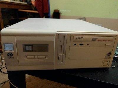
I recently got a new Pentium-based machine. It has a nice little horizontal AT case with a Turbo button and a MHz LED. And ever since I've got this machine I've tried my best to get it working.

AsopS8x.jpg
Filename
AsopS8x.jpg
File size
33.24 KiB
Views
999 views
File license
Fair use/fair dealing exception

Initially, it had two triple wires, one labled TURBO_SW and the other one had no lable:

2016-06-24 01.06.36.jpg
Filename
2016-06-24 01.06.36.jpg
File size
81.84 KiB
Views
1001 views
File license
Fair use/fair dealing exception

One of them could be easily connected to the motherboard headers, the other one (unlabeled) was too short. So at first I assumed one was for the switch and the other one was for the LED. And so, the only way I could get the LED to work is by either getting a longer AT board with proper headers (which is a bit tricky) or by somehow swapping/extending the wires so they could reach the motherboard.

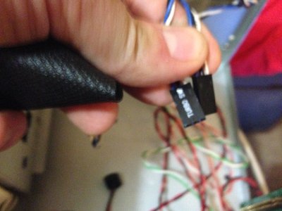
After getting rid of a small heap of glue I could see where the wires were actually going to. And I finally realised that they are both only connected to the Turbo button:

2016-06-24 01.06.21.jpg
Filename
2016-06-24 01.06.21.jpg
File size
78.28 KiB
Views
1001 views
File license
Fair use/fair dealing exception

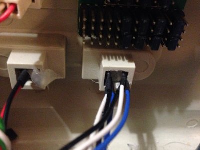
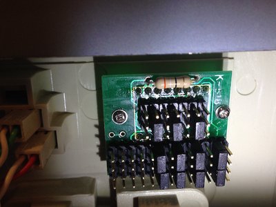
So, I assume none of these wires actually power the MHz LED, and my system simply came without the wires needed. Here is the back of the MHz LED:

2016-06-24 01.05.49.jpg
Filename
2016-06-24 01.05.49.jpg
File size
116.07 KiB
Views
1001 views
File license
Fair use/fair dealing exception

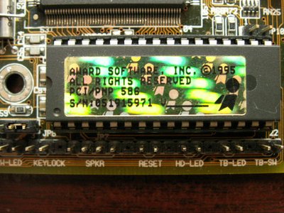
And here are the motherboard headers:

PICT3328.JPG
Filename
PICT3328.JPG
File size
163.58 KiB
Views
1001 views
File license
Fair use/fair dealing exception

So, how do I get this to work?

1) Which pins of the LED are actual headers that the wires should be attached to?
2) What kind of wires do I need?
3) How do I know at what speed does my CPU run at?
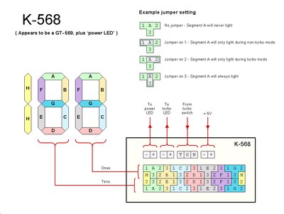
4) How do I get the LED to show the proper frequency for turbo/deturbo state? I assume this is what the jumpers are for.

MR BIOS catalog
Unicore catalog

Reply 1 of 4, by Robin4

User metadata
Rank l33t
Rank
l33t

First you need to find out on the K-518 display the configuration headers.. (where you need to connect the blank blue / black / white wire (for switching) and the red / black (5 volt power supply) on your k-518 display..

1. You need a 5volt power source cable from the psu to the K-518 display.. Watch out, this 5 volt mus not exceed 5 volt, otherwise you burn out the display.. These displays are very oversensitive for higher voltages.
( there need to be some markings on the back side of this k-518 which indicates Positive + and negative - (the red wire have 5 volt on it and needs to connected with the postive + terminal) the black wire is for the negative connection.. If you connect this right the K-518 display starts running.)

( i cant see the right terminals on picture 4)

2. Then the black, blue and white wires ( you only need two of them..) (when using black and white) the turbo button will set on turbo when the turbo button is not pressed ( in pressed mode the turbo goes off)
When using the blue and black wire (its the other way around) Then turbo will working when pressed the turbo button,if the button is de-pressed the turbo function is off

The connector with `turbo SW` written on it needs to connected with the turbo SW on your motherboard.. The blank one needs to connected with the K-518 display (you need to look for the right connection)

( the bleu, black, white wires are indeed not for power the display, but this is for switching the display and turbo led in these two modes (non-turbo and turbo mode)

You need a seperate black / red wire that mostly are on those molex splitter cables (or just use the 5v red and black negative from your power supply.

~ At least it can do black and white~

Reply 2 of 4, by tyuper

User metadata
Rank Newbie
Rank
Newbie

I have the same LCD display in one of my cases. Here's pinout of first row:
|T+| |T-| |L| | C| |H| |5V| |G|

T+ and T- are power for turbo diode.
Low, Common, High are signal coming from motherboard thru turbo button to LCD. When you connect High and Common on motherboard, the LCD will show f.e 25 MHz with turbo depressed and 100 MHz with turbo pressed. Connected Low and Common works vice versa.
5Volt and Ground are power for LCD.

For configuring numbers on display, you will need to experiment, because there isn't on the web accurate map of K-518 which would tell what segment will lit up depending on if turbo is pressed or it's not. Attached picture should give you an idea on how to solve this puzzle 😀

LED display - K-568.jpg
Filename
LED display - K-568.jpg
File size
234.6 KiB
Views
987 views
File license
Fair use/fair dealing exception

Reply 3 of 4, by jheronimus

User metadata
Rank Oldbie
Rank
Oldbie

Welp, plugged all the wires just like Robin4 said — there actually was a double wire going from the PSU via a Molex connector. It worked perfectly at first: it showed 133 (my CPU actual frequency) with Turbo button released and did not show anything with Turbo button pressed.

After a few minutes some segments stopped working or began blinking. After a few minutes more, the LED stopped working altogether.

Gonna try and reshuffle the wires/jumpers this weekend.

MR BIOS catalog
Unicore catalog

Reply 4 of 4, by jheronimus

User metadata
Rank Oldbie
Rank
Oldbie

So, I've managed to get this all to work. Turns out, I mistook the connectors and used t+/t- instead of the 5V ones, which fried the LED. Found an S-305H on a spare case which fit. Used the schematics on the site and it now shows the proper frquency.

The problem now is that the Turbo button doesn't really do anything. According to NSSI, my CPU benchmark stays the same regardless of the button.

MR BIOS catalog
Unicore catalog