VOGONS


Reply 20 of 37, by luckybob

User metadata
Rank l33t
Rank
l33t
feipoa wrote:

Where did you all go to university for EE?

I went to a technical college here locally. Spent 3 years there. Walked out with what I believed a start to a new life only to find it was practically worthless. The education I got WAS good, but the school was not. We had a lab where you were encouraged to design your own projects from start to finish. printed PCB in hand. I still have the registrations for 5 copies of Pcad... I don't regret going there. I regret not having the resolve to goto a actual proper university and get a proper degree that would get me a job.

My stance on caps is very simplistic. Just just something quality with a proper rating. Special caps, with special properties is the domain of analog design. Analog is black magic voodoo.

It is a mistake to think you can solve any major problems just with potatoes.

Reply 21 of 37, by orcish75

User metadata
Rank Member
Rank
Member

It is absolutely fine to use 16V capacitors rather than the 25V ones. If you have 16V running through your motherboard, the capacitors will be the least of your worries.. Solid polymer capacitors have a much lower ESR than standard electrolytics, however as stated above, they are larger for a given voltage and capacitance (and more expensive)

Reply 22 of 37, by Jepael

User metadata
Rank Oldbie
Rank
Oldbie
feipoa wrote:

... It was commented that using larger voltage-rated electrolytic capacitors disipate heat more readily and thus will likely last longer than lower rated caps ...

TELVM wrote:

IMHO it's larger can size, not larger voltage rating, what increases heat dissipation in lythics. That said, at the same capacitance a cap with higher voltage rating will most probably be of a larger can size, so will have better heat dissipation.

I would not call it penny-pinching, I'd call it product engineering, whether to deliver a cheaper product to consumers and/or get more profit.
There's so much more to it than just ESR.

To approach this from different angles:
-the physical size (volume) of a capacitor is approximately determined by product of capacitance * voltage
-therefore, at the same capacitance value, a cap with higher rated voltage usually needs to be physically larger in size
-physically larger size caps usually have lower ESR so it just does not heat as much to begin with, and because it's larger it can radiate heat away more efficiently
-for a same capacitor physical size (volume), sometimes ESR is pretty same, but sometimes a capacitor with larger capacitance and lower voltage rating may have lower ESR
-at high temperatures and ripple currents, the capacitor can't withstand the rated voltage, it needs to be derated about 20%, and the more you derate the longer the cap life is. (the 20% value should be good for aluminium electrolytics, some other types of caps may need to be derated by 50%, i.e. for 12V system you need at least 24V cap).

So in short, back then the motherboard designers needed a cap that would fulfill many parameters such as certain capacitance limits, certain ESR limits, certain lifetime limits, certain heating limits, certain physical size limits, so even if it's only a 12V system they chose a 25V cap they had available because it fulfilled all the specs at cheaper price than any 16V cap they had available.

Having said that, a modern 16V polymer cap may be fine, just check if it needs derating or not, to work with up to 12.6V coming from PSU (5% tolerance).

Reply 23 of 37, by feipoa

User metadata
Rank l33t++
Rank
l33t++
FesterBlatz wrote:

In fact there's actually such a thing as having TOO low of an ESR when considering linear voltage regulator design-specifically those incorporating LDOs such as those common on 486 motherboards and upgrade modules. In these cases having too low of an ESR can prevent the LDO's output loop from establishing a sufficient amount of phase lead necessary for stable operation.

Is the same arguement true for non-LDO linear regulators? If not, then is there a general rule for how much dropout is "low"? 0.25 V dropout is certainly very low. 1.5 V is also considered low. 3.0 V is not really considered "low".

FesterBlatz wrote:

Rather than focusing on only a few favorable specifications, it's important to understand how ALL of its attributes effect the system as a whole and choose the best overall fit for that specific application.

This is pretty vague. Could you elaborate on this? I have, in the past, read to varying degrees on this subject, but have yet to find information that sticks.

Plan your life wisely, you'll be dead before you know it.

Reply 24 of 37, by feipoa

User metadata
Rank l33t++
Rank
l33t++
Jepael wrote:

-at high temperatures and ripple currents, the capacitor can't withstand the rated voltage, it needs to be derated about 20%, and the more you derate the longer the cap life is. (the 20% value should be good for aluminium electrolytics, some other types of caps may need to be derated by 50%, i.e. for 12V system you need at least 24V cap).

How do you determine if the capacitor needs to be derated [by 50%]? Which I imply as needing to source a capacitor with a 50% higher voltage rating. I've noticed on some of these niob oxi caps that those from the same series with a higher ESR have a lower ripple current.

Jepael wrote:

...a modern 16V polymer cap may be fine, just check if it needs derating or not, to work with up to 12.6V coming from PSU (5% tolerance).

Again, how do we check for this within a given design?

EDIT: This article shows calculated examples of when not even a 50 % derating is sufficient, and a case where 20% is sufficient for tantalum and niob oxide caps. http://www.avx.com/docs/techinfo/VoltageDerat … mCapacitors.pdf

Last edited by feipoa on 2017-03-30, 21:41. Edited 1 time in total.

Plan your life wisely, you'll be dead before you know it.

Reply 25 of 37, by feipoa

User metadata
Rank l33t++
Rank
l33t++
luckybob wrote:
feipoa wrote:

Where did you all go to university for EE?

I went to a technical college here locally. Spent 3 years there. Walked out with what I believed a start to a new life only to find it was practically worthless. The education I got WAS good, but the school was not. We had a lab where you were encouraged to design your own projects from start to finish. printed PCB in hand. I still have the registrations for 5 copies of Pcad... I don't regret going there. I regret not having the resolve to goto a actual proper university and get a proper degree that would get me a job.

My stance on caps is very simplistic. Just just something quality with a proper rating. Special caps, with special properties is the domain of analog design. Analog is black magic voodoo.

When I was in the US, I remember there being commercials on television advertising Devry and ITT Technical schools. I personally don't know how good or bad the education is there, but there is a stigma associated with them and employeers aren't too keen on these graduates. I think because mostly the kids who didn't do well in high school and community college join these schools. I really appreciated the broader range of education that a regular university or college offers. Even more so if you start out at a community college and transfer into a university program, you tend to take even more general education courses.

Plan your life wisely, you'll be dead before you know it.

Reply 26 of 37, by luckybob

User metadata
Rank l33t
Rank
l33t

yea, ITT. I had several teachers there, whom worked both at ITT and colorado state. So I got the exact same level of education, I even had the teachers come in when I tried to transfer my "Credits" and theys till would not take them. I'd basically have to start my education over. So rather than go deep into debt, I moved on.

It is a mistake to think you can solve any major problems just with potatoes.

Reply 27 of 37, by Jepael

User metadata
Rank Oldbie
Rank
Oldbie
feipoa wrote:

Is the same arguement true for non-LDO linear regulators? If not, then is there a general rule for how much dropout is "low"? 0.25 V dropout is certainly very low. 1.5 V is also considered low. 3.0 V is not really considered "low".

No, I think normal linear regulators usually don't have a limit for minimum ESR, I can't recall ever seeing one that does. Actually the definition of an LDO is not the dropout itself, but the internal topology (schematics) how it works to provide that low dropout. Normal linear regulators have the pass transistor in emitter follower configuration so they need more voltage drop to operate, while LDO regulators have the pass transistor the other way around so it can be run up to saturation. The LDO topology has by itself very unstable voltage regulation feedback loop and it will oscillate unless compensated with extra zero in the feedback loop, and it can be done with adding a resistor in series with the capacitance, or just selecting a capacitor that has large enough ESR so no extra components are needed. So this basically rules out ceramic caps (too low ESR) and aluminium electrolytics (ESR changes too much due to temperature) and leaves you with tantalums.

feipoa wrote:

How do you determine if the capacitor needs to be derated [by 50%]? Which I imply as needing to source a capacitor with a 50% higher voltage rating. I've noticed on some of these niob oxi caps that those from the same series with a higher ESR have a lower ripple current.

Manufacturer has datasheets and application notes so they should give some guidance how to use the part. And yes that ESR/current is a good observation, as for the same ripple current, a higher resistance part heats up more than a lower resistance part, so they specified lower current for the higher ESR part so that it does not heat too much.

feipoa wrote:

Again, how do we check for this within a given design?

EDIT: This article shows calculated examples of when not even a 50 % derating is sufficient, and a case where 20% is sufficient for tantalum and niob oxide caps. http://www.avx.com/docs/techinfo/Voltag ... citors.pdf

That was an interesting read. Yes voltage derating does not really mean anything if the cap has a max current limit, or some other limit, then it must be obeyed. Same with all other parameters like temperature. It's not very easy to determine even when you know what you are doing in a given design, and much more impossible when replacing caps in a device because you don't really know the required parameters.

So that's the hard part when replacing for example motherboard caps. You can't really know just based on just ESR or price if the caps will work. If the caps blow up immediately, they were obviously not meant for the job. If they work for a year and start leaking, they could not handle the environment in the long run. If they work for ten years, something else will break first.

I personally think hardest part of designing or building a device is how to power all the chips, but then again I am not an expert on the subject.
I found an interesting read though, about how P3 cpu should be powered : http://www.intel.com/design/pentiumiii/applnots/24508501.pdf

Reply 28 of 37, by gdjacobs

User metadata
Rank l33t++
Rank
l33t++
Jepael wrote:
feipoa wrote:

Is the same arguement true for non-LDO linear regulators? If not, then is there a general rule for how much dropout is "low"? 0.25 V dropout is certainly very low. 1.5 V is also considered low. 3.0 V is not really considered "low".

No, I think normal linear regulators usually don't have a limit for minimum ESR, I can't recall ever seeing one that does. Actually the definition of an LDO is not the dropout itself, but the internal topology (schematics) how it works to provide that low dropout. Normal linear regulators have the pass transistor in emitter follower configuration so they need more voltage drop to operate, while LDO regulators have the pass transistor the other way around so it can be run up to saturation. The LDO topology has by itself very unstable voltage regulation feedback loop and it will oscillate unless compensated with extra zero in the feedback loop, and it can be done with adding a resistor in series with the capacitance, or just selecting a capacitor that has large enough ESR so no extra components are needed. So this basically rules out ceramic caps (too low ESR) and aluminium electrolytics (ESR changes too much due to temperature) and leaves you with tantalums.

Here's a paper that explains the issue. It's not a function of the topology but the behavior of the pass element (in this case) which results in more complex and impedance sensitive functioning.
http://www.ti.com/lit/an/slyt194/slyt194.pdf

All hail the Great Capacitor Brand Finder

Reply 29 of 37, by feipoa

User metadata
Rank l33t++
Rank
l33t++
luckybob wrote:

yea, ITT. I had several teachers there, whom worked both at ITT and colorado state. So I got the exact same level of education, I even had the teachers come in when I tried to transfer my "Credits" and theys till would not take them. I'd basically have to start my education over. So rather than go deep into debt, I moved on.

Academia is a dirty business. In my opinion, their primary goal is to make money and to award those who work in the establishment. I would really like to see legislation which restricts the quantity of university degrees awarded to a particular field based on recent hiring demand from industry.

I remember someone telling me that instructors are Devry/ITT are paid heavily.

Interestingly, there isn't the same stigma on technical schools in Canada, at least not from my observation. I knew someone who transfered his undergraduate credits from one to attend a regular university.

Jepael wrote:

No, I think normal linear regulators usually don't have a limit for minimum ESR,

They do seem a bit more relaxed, though I did run across one recently which specified an ESR of 200 - 2000 m-ohm range when the output capacitor was less than 47 uF. For greater than 47 uF, ESR should be less than 1000 m-ohm. It recommended cermaic X7R/X5R caps, but I couldn't find an ESR value for these at 100 KHz, but I assume they are all less than 1 ohm.

I'm working on a design now, which uses either a linear or switching regulator. I'll likely use a switching because it seems they are more likely not to require a heatsink. For both, I am finding that the dropout is greater than I expected and larger than the spec sheet calls for. And I am way under the max current load of the regulator. I might try switching to some of these ultra-low dropout regulators (0.2 - 0.6V) which are more for a narrow range of low input/output voltages.

It would be nice if the spec sheets specified dropouts for various input and output voltages. Interestingly, the dropout figures for the Texas Instrument branded 2596 switching reg appears to have less dropout compared to the ON Semi branded LM2596. The cost of the TI is almost 3x more and I bought the ON device. I've been using a low wattage resistor to simulate load at max typical current (500 mA).

I did notice how the ON and TI spec sheets for the 2596 seem to go into great detail as to the input and output capacitors. It seems like a big deal for switching regs. The gist of it was, "go low ESR, but not too low - if you go too low, then you need to add a compensation capacitor." Unfortunately, it didn't really say what is the ideal ESR, just that <50 m-ohm is too low. So does that mean 55 m-ohm is just nice, or will there be some small unwanted effects?

Plan your life wisely, you'll be dead before you know it.
Reply 30 of 37, by ahtoh

User metadata
Rank Member
Rank
Member
simbin wrote:
I recently picked up a GA-5AX v5.2 that randomly fails to post. Upon inspection, I noticed a couple of the 330uF 25v caps near t […]
Show full quote

I recently picked up a GA-5AX v5.2 that randomly fails to post. Upon inspection, I noticed a couple of the 330uF 25v caps near the CPU are bulging.

Phil is recommending 16v solid caps instead of the original 25v rating. Is that okay?
http://www.philscomputerlab.com/ga-5ax-capaci … -replacing.html

I just want to make sure I do right by this very special motherboard 😀

If it makes any difference, I intend to run a K6-III 400 1.6v @ 500MHz.

Did you replace the caps? Did it work?
Which ones did you use?

Reply 31 of 37, by Nemo1985

User metadata
Rank Oldbie
Rank
Oldbie

Sorry for the bump, I'm looking to recap the same motherboard, which caps have been used and how was the result?
I don't mind spending a reasonable amount of money for this board so i'm looking for very good caps
Also the link from Phil's doesn't work anymore :\

Reply 32 of 37, by Nemo1985

User metadata
Rank Oldbie
Rank
Oldbie

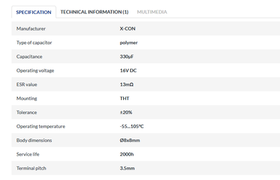
I was wondering if those caps will be ok to do a full recap of the board:

capacitor.png
Filename
capacitor.png
File size
17.1 KiB
Views
721 views
File license
Public domain

Is the ESR too high? The terminal pitch is right?

Thank you for any answer

Reply 33 of 37, by quicknick

User metadata
Rank Oldbie
Rank
Oldbie

I don't have the 5AX (had a non-working one, gave it away), but if the caps are the same 330uF/25V that Gigabyte loved to use on a few models during late 90s/early 00s, I replaced them on a couple of boards (7VX Slot A & 7VTXH+ Socket A) with Panasonic EEUFM1E331 electrolytics. These are 10mm in diameter, if the 5AX uses 8mm please disregard the above advice.

13mohm is a very good ESR value, doubt that the originals were anywhere near that if they weren't from a reputable brand and ultra-low-ESR series. If the diameter matches, the terminal pitch will match also.

Reply 34 of 37, by Nemo1985

User metadata
Rank Oldbie
Rank
Oldbie

Thank you very much for the tip, I have my gigabyte in a case, so I can't really see the dimension of the capacitors, I have to watch the internet pictures.
People before me switched down to 16v capacitors since 25v were probably used to achieve longer lifespan.
Do you think the panasonic will be better than the polymer caps I have chosen?

Reply 35 of 37, by quicknick

User metadata
Rank Oldbie
Rank
Oldbie

I kept the original caps from the GA-7VX, they are G-Luxon 330uF/25V and they still measure surprisingly good, around 27-30 mohm. The Panasonic FM of same ratings and 10mm diameter are 38 mohm according to the datasheet.

The 7VTXH+ was fitted with Choyo "brand" caps which were bloated so I threw them away. They measured 0...15uF and ESR was around 4-10 ohms.

The polymers that you linked above are obviously much better. I suggest taking out the board and measuring the diameter, it will be hard and unsightly to fit 3.5mm pitch caps in holes with 5mm spacing. Also, I think the board must be using at least a few caps of a different rating, perhaps near the CPU VRM. Both my Gigabyte boards use 1200uF/6.3V along with the 330/25 ones, and these I've replaced with Panasonic FR.

Edit: definitely (at least) two types/dimensions of capacitors are used on the 5AX, just looked at some pics.

Reply 36 of 37, by Nemo1985

User metadata
Rank Oldbie
Rank
Oldbie

Thank you, I watched the caps of the ss7 boards (asus p5a for example) and yes there are 2 different size of caps but still they have very same capacitance and voltage (v6.3 and 1000uf) there are just 2 that are a bit higher.
Anyway I will take the board out from the case, give it a look and report back.

Reply 37 of 37, by Nemo1985

User metadata
Rank Oldbie
Rank
Oldbie

I just checked, there are:
17 v25 330uf 3.5
8 v25 330uf 5
As supposed the capacitors have the same voltage and capacitance, the difference is the the dimension and the distance between holes.
This might be a problem because there is only one kind of polymer capacitors with 5mm and they are not cheap at all.
As a side note I was sure it used the G revision of the chipset, while it uses the E revision, so only the bugged asus p5a has the newest revision?