I don't know how helpful it will be, but there's a thread at badcaps.net about recapping this board:
http://www.badcaps.net/forum/showthread.php?t=1583
There's a picture there that shows some of the caps, but you have to be registered to see it. I'm not sure if it's okay for me to copy it here or if that would start some diplomatic incident with the other forum.
There's also a picture here which shows some of the caps:
Re: Hardware Gore!
I think the KA7 and KA7-100 are the same PCB, so the same caps are probably used on both.
If you check resistances with a multimeter, you can figure out which caps are in parallel with each other and what circuit they're connected to. That can help to make an educated guess about what caps to put in.
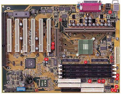
ABit boards from that period usually have a lot of 1000uF and 1500uF 8mm caps, especially in the VRM area. The highest voltage that's in that area is probably +5V. They didn't use +12v for the CPU VRM back then.
Pictures show four 2200uF 6.3v caps arranged in a square, halfway up the CPU slot, between the CPU and an inductor. You can see them in the VOGONs picture linked above.
The main "line" of caps going alongside the CPU slot has some 1500uF caps, but I don't know if they're all 1500uF or if some are 1000uF.
The badcaps thread showed another 8mm cap on the other side of the CPU slot between the CPU and the ATX power connector. It's 1500uF 6.3v.
You can use a multimeter to figure out which of the caps next to the CPU are on Vcore. You'll probably find that most of those caps are electrically on the same circuit in that row next to the CPU. Those were probably all the same originally. You can probably put 1500uF 6.3v (or 1500uF 10v, whatever is easier to find) in all those spots and it would probably work fine.
For CPU Vcore, there is a relationship between capacitor ESR and how much capacitance is necessary. If your replacement caps have better specs than the originals, then they might not have to be 1500uF.