VOGONS


Reply 560 of 1184, by rasz_pl

User metadata
Rank l33t
Rank
l33t

200-300mV noise on output of linear regulator is indeed terrible. Mic was sourced from reputable distributor, right?
LDOs need certain amount of finely tuned ESR on the output to properly regulate (used for feedback). My guess is Gainberry designer actually calculated it or arrived at the number of caps experimentally to suit LT regulator optimally. Yours is oscillating.

https://toshiba.semicon-storage.com/info/appl … 8.pdf?did=67687
"Introducing a zero at fz using the equivalent series resistance (RESR) of an output capacitor."

file.php?id=48956&mode=view
that forest of 15 small caps surely doesnt hurt

feipoa wrote on 2022-12-01, 11:20:

I'm not sure why the reading is so different. Although I don't have a DMM that is true RMS, it should do some averaging to approach RMS.

RMS is taken into account in AC mode. True RMS meters dont have infinite bw, its tens to hundreds of KHz.

feipoa wrote on 2022-12-01, 11:20:

However, even though the CPU doesn't get hot, I needed to affix a fan. Without the fan, Quake crashed after 5 minutes. The CPU was only getting up to about 33 C when it would crash. I am using a very low CFM fan, more on that later on. The ambient temperature during test was 16 C, so your results may vary.

What is the temperature of regulator is the more important question 😀 Its a heater, drop resistor. Its burning 30% of the power CPU is, but at significantly smaller surface area.

All in all if it works it works, seems CPU doesnt care all that much about supply quality.

>Are the regulators between the two units pin compatible?

no
https://ww1.microchip.com/downloads/aemDocume … DS20005685B.pdf
https://www.analog.com/media/en/technical-doc … eets/1528fb.pdf
Last edited by rasz_pl on 2022-12-01, 13:45. Edited 1 time in total.

Open Source AT&T Globalyst/NCR/FIC 486-GAC-2 proprietary Cache Module reproduction

Reply 561 of 1184, by Mike1978

User metadata
Rank Newbie
Rank
Newbie

Wow does this mean we are nearing a final working interposer for a 386 to 486 full sized chip.

This is awesome work guys and been following this for a long time hoping you’d crack it.

It maybe just in time for my find of an intel inboard 386/pc that I’d love to upgrade with a real 486 / 586 CPU

Would this perform better than a Cyrix cx486drx2 (clock doubled) 386 to 486 cpu I have ?

Amazing thread and great collaboration effort.

Reply 562 of 1184, by Sphere478

User metadata
Rank l33t++
Rank
l33t++

^ it appears we already have one. 😀 we are ironing out the final details. But this one seems fully functional!

At feiopa
If you determine a different configuration for capacitors let me know and I can try to accommodate them in design but there are limits obviously. The sub surface in the middle is basically solid packed with traces 🤣. So random vias down to the power planes for small caps is out, gonna have to route on the top layer like I did.

I guess this means that encapsulating all those traces in so much ground plane must have helped. I also would like to improve power quality. I am suspecting that it may be from the different regulator? Do you agree? But the change in frequency is odd.

I would be very curious to see the gerbers of that oem interposer. Though it seems not necessary, if anyone reading this ever comes across a busted one sand it down and photograph the layers if you can. But only if it is totally trashed. We don’t want to destroy a working/salvageable piece of history.

Sphere's PCB projects.
-
Sphere’s socket 5/7 cpu collection.
-
SUCCESSFUL K6-2+ to K6-3+ Full Cache Enable Mod
-
Tyan S1564S to S1564D single to dual processor conversion (also s1563 and s1562)

Reply 563 of 1184, by rasz_pl

User metadata
Rank l33t
Rank
l33t

If you look at the caps on Gainberry they dont all just go into power and ground planes. Its important for caps to be placed in a way flowing current actually passes over their pads.

Open Source AT&T Globalyst/NCR/FIC 486-GAC-2 proprietary Cache Module reproduction

Reply 564 of 1184, by maxtherabbit

User metadata
Rank l33t
Rank
l33t
Mike1978 wrote on 2022-12-01, 13:43:
Wow does this mean we are nearing a final working interposer for a 386 to 486 full sized chip. […]
Show full quote

Wow does this mean we are nearing a final working interposer for a 386 to 486 full sized chip.

This is awesome work guys and been following this for a long time hoping you’d crack it.

It maybe just in time for my find of an intel inboard 386/pc that I’d love to upgrade with a real 486 / 586 CPU

Would this perform better than a Cyrix cx486drx2 (clock doubled) 386 to 486 cpu I have ?

Amazing thread and great collaboration effort.

I think it's important to point out this device will NOT work with a *real* 486/586 CPU

It's purpose built for a very specific chip

Reply 565 of 1184, by Sphere478

User metadata
Rank l33t++
Rank
l33t++
maxtherabbit wrote on 2022-12-01, 15:29:
Mike1978 wrote on 2022-12-01, 13:43:
Wow does this mean we are nearing a final working interposer for a 386 to 486 full sized chip. […]
Show full quote

Wow does this mean we are nearing a final working interposer for a 386 to 486 full sized chip.

This is awesome work guys and been following this for a long time hoping you’d crack it.

It maybe just in time for my find of an intel inboard 386/pc that I’d love to upgrade with a real 486 / 586 CPU

Would this perform better than a Cyrix cx486drx2 (clock doubled) 386 to 486 cpu I have ?

Amazing thread and great collaboration effort.

I think it's important to point out this device will NOT work with a *real* 486/586 CPU

It's purpose built for a very specific chip

Yeah, perhaps we could put something on silk screen. Are there any other cpus at all this will work with? If so, we should list them on the silk
Screen.

I would like to include that in a visible area, and a full parts list on the silk screen in a area that will be hidden once assembled.

I can’t recall if I commented on this, but I kinda doubt that there will be much power quality difference motherboard to motherbord (but possible) I bet it has more to do psu to psu.

Obviously in feiopa’s tests I believe he used the same system for both, so the only variable was the interposer and the regulator/caps on it.

So I am trying to decide how much we can rely on his optimal capacitor config that he figures out..

I thibk to a degree, it should be fine, but perhaps some other systems may be able to squeeze out a tiny bit better with different configs.

In any case, I am super curious how it does with a different regulator or a separate psu, like a lab quality one.

Sphere's PCB projects.
-
Sphere’s socket 5/7 cpu collection.
-
SUCCESSFUL K6-2+ to K6-3+ Full Cache Enable Mod
-
Tyan S1564S to S1564D single to dual processor conversion (also s1563 and s1562)

Reply 566 of 1184, by RayeR

User metadata
Rank Oldbie
Rank
Oldbie

Congrat...
Could you give a link to pins/headers that you used to mate with MB socket?

Gigabyte GA-P67-DS3-B3, Core i7-2600K @4,5GHz, 8GB DDR3, 128GB SSD, GTX970(GF7900GT), SB Audigy + YMF724F + DreamBlaster combo + LPC2ISA

Reply 567 of 1184, by feipoa

User metadata
Rank l33t++
Rank
l33t++

rasz_pl, thanks again for your remarks. Yes, the 200 mV noise that I ended up with (before clock doubling enabled) is indeed horrible and is why I immediately sought advice before posting any other findings or testing in more depth. Like you, I first thought, 'these damn Chinese eBay counterfeit parts...' However, I still had a digikey sourced regulator of the same brand that I put on the Blavius model. I desoldered it an put it on the feipoa-sphere unit. The regulator output was identical.

That forest of caps on the Gainbery is the most I've seen on a 486 interposer. Normally, the Evergreens had 4-8 caps on the bottom. I may even have a regulator with less. I need to check again. While most interposer came with Am5x86, the Gainbery came with an IBM 5x86 chips.

The temperature of the regulator was the same as the CPU, around 33 C. The regulator backing plate is touching the heatsink.

Mike1978, yes it will perform better than a DRx2-66, provided your motherboard doesn't complain about the CPU. I've never had an issue getting an SXL2 CPU working in ~10 motherboards.

I suspect the various input/output signals from/to the CPU are interfering with Vcc. It wasn't clear to me why no value of capacitor helped much in this regard. Makes me think the issue is with trace to trace parasitics, perhaps from the tight packing of the traces, poor JLCPCB inter-layer interconnections, perhaps from the through-hole to through-hole design... or maybe there's one blob of solder barely touching where it shouldn't. I suppose assembling another unit will help answer the later.

It would be interesting to take my red prototype and put it in the one motherboard it sort of worked on and see what kind of noise there is on Vcc. I cannot just put the red prototype in the board on the testbed because it doesn't work in that board. And when it doesn't work, the Vcc output is clean and flat.

I can power it with my bench top DC supply and check the waveform. However, I don't exactly have name brand high quality equipment. I suspect it will look the same.

Sphere, no other CPUs will work on this unit. It is merely a simple pin re-mapping board for a specific CPU. If you want to use a traditional 486 on a 386 board, you need a Transcomputer module. Photos found on Vogons listed by me.

Yes, I want to try another motherboard to check Vcc. I've already tried an AT PSU and an ATX-AT PSU. No change in Vcc waveform.

I forgot to mention what the noise means for overclocking. With the Improve-It + Gainbery, I could run 80 MHz at 3.75 Vrms, while with the exact same CPU in the feipoa-sphere unit, I had to run it at 3.80 Vrms.

Another idea might be to re-run the PCB with the pinouts for a different regulator, but at $81 USD per run, I'm not paying.

Rayr, I'll provide a BOM in the next few days.

Plan your life wisely, you'll be dead before you know it.

Reply 568 of 1184, by pentiumspeed

User metadata
Rank l33t
Rank
l33t

Have you confirmed that adapter's ground plane is not oscillating? For this, oscilloscope's ground clipped to the motherboard's ground and your probe on the adapter's ground plane?

The processor's white noise is correct, but the voltage ripple is too much, all of this from linear regulator oscillation. Need to keep tantalums there but add smaller MLCC capacitors in parallel on input and output. *Also* add small capacitor to the adj pin of regulator just in case? This is important that ground and voltage planes is very strong, very low resistance, in cases designers had to have more vias and two or four vias per pad for capacitors and wide tracks.

Cheers,

Great Northern aka Canada.

Reply 569 of 1184, by Sphere478

User metadata
Rank l33t++
Rank
l33t++

can you clarify what your conclusion is, do you believe that the noise is due to the regulator, wrong cap combo, wrong cap placement? or due to the pcb signals cross talking or due to both.

Any chance you could take your oscilloscope and probe the various signals to try to find one that correlates perhaps if we can find which signals are generating this cross talk if indeed that is what is happening we may be able to isolate it better but gotta know which ones are problem child.

But that doesn’t make sense to me,

How could digital signals be inducing a 700hz oscillation on the power plane.

I would be more worried about the opposite, oscilations on the power plane messing with signals for the bus causing errors haha.

Oscilations on the power plane in general should come from these sources, as far as I know, feel free to correct

induced ones from high currents traveling in parallel, (I don’t think this is what is happening)

Uneven loading (it’s a processor, uneven loading is probably with the territory I would assume

Uneven generation.

So those are the sources I can think of,

Ways to smooth out those sources:
Capacitors, inductors, better smoother generation, less induced interference, more even loading.

We aren’t going to change the loading aside from changing voltage/what we are doing with cpu.

We can go to a different regulator

If we can identify some sort of source that is inducing this signal I can try to move it or isolate it.

We can try more capacitor experiments.

You could try soldering small caps to vcc/vss pins that are close to one another on the bottom of large socket.

But anyway, I want to clarify where you think the source is,

See if you can run the processor on a parallel bank of 18650 laptop lithium ion cells and read what you have. If your lab psu isn’t up to snuff.

That will tell us for sure if the interference is from the pcb.

Anyway,like I said, I’m a little unclear on where you think it is coming from.

But, 🤣, it seems like it is a full success if you can clock as high despite it haha

Sphere's PCB projects.
-
Sphere’s socket 5/7 cpu collection.
-
SUCCESSFUL K6-2+ to K6-3+ Full Cache Enable Mod
-
Tyan S1564S to S1564D single to dual processor conversion (also s1563 and s1562)

Reply 570 of 1184, by Sphere478

User metadata
Rank l33t++
Rank
l33t++

If that ground plane is oscillating I’m gonna be at a loss as to what to do about it, it’s connected to every single vss pin and interconnected to its self all over the place, i can’t think of a way to make it more solid. Like seriously, that ground plane is amazing for such a tangled spaghetti that had to pass through it. I put a lot of effort into exactly this. I really hope that it isn’t oscillating.

I would say I could add a ground strap pad to mobo screw. But it should already have a solid path from the socket pins.

Sphere's PCB projects.
-
Sphere’s socket 5/7 cpu collection.
-
SUCCESSFUL K6-2+ to K6-3+ Full Cache Enable Mod
-
Tyan S1564S to S1564D single to dual processor conversion (also s1563 and s1562)

Reply 571 of 1184, by feipoa

User metadata
Rank l33t++
Rank
l33t++

One other idea I have is to muck up one unit using another VRM, but this will not look pretty. I have probably have 10 different brands of VRM's sitting in my bin, maybe 4 more which are ultra-low dropout.

pentiumspeed wrote on 2022-12-01, 23:01:

Have you confirmed that adapter's ground plane is not oscillating? For this, oscilloscope's ground clipped to the motherboard's ground and your probe on the adapter's ground plane?

I haven't checked for oscillation on the ground plane, but intend to look at this to night. Could be from a ground loop? What I have tried is connecting the scope's ground clip to the GND on the molex, but the resultant waveform looked identical to clipping the scope's GND on the VRM tab.

pentiumspeed wrote on 2022-12-01, 23:01:

The processor's white noise is correct, but the voltage ripple is too much, all of this from linear regulator oscillation. Need to keep tantalums there but add smaller MLCC capacitors in parallel on input and output. *Also* add small capacitor to the adj pin of regulator just in case? This is important that ground and voltage planes is very strong, very low resistance, in cases designers had to have more vias and two or four vias per pad for capacitors and wide tracks.

You may have missed it in the wall of photos, but I already tryied adding bypass to the adjust pin, that is, a ceramic in paraellel with R2. See previous statement here:

feipoa wrote on 2022-12-01, 10:16:

I tried adding a ceramic bypass to the voltage set resistor R2, but it didn't help. I tried a few values, I think 15 nF, 47 nF, and 10 uF. No effect with the lower values and the larger value altered the output voltage enough that it wasn't showing on the current scale I had set on the scope.

I also noted ceramic attempts on Vin and Vout here:

feipoa wrote on 2022-12-01, 10:16:

Then tried adding a 47 nF ceramic capacitor, so (22 uF + 150 nF + 470 nF) tantalum + 47 nF ceramic. No discernible improvement.... I decide to try adding ceramic to Vin, although this 5 V line looks fine. I add 10 nF, 47 nF, 100 nF, 220 nF... Didn't help... I also tried leaving the 22 uF, 150 nF, 220 nF, 470 nF tantalums and add on top a 15 nF ceramic, but the waveforms still did not change.

I appologise if my wall of photos dialogue was not clear enough. It took hours to post all of that and I was getting tired. Do you have specific MLCC values you'd like me to try, and if so, what values and placed where?

What I have not tried, which I may try with the extra board I make for sphere, is not putting any tantalums in the centre region, but rather all ceramics 10nf, 47nf, 100nf, 220nf. On that unit, I will then use 22 uF tantalum for VRM output and 10 uF ceramic on VRm input.

Sphere478 wrote on 2022-12-01, 23:10:

can you clarify what your conclusion is, do you believe that the noise is due to the regulator, wrong cap combo, wrong cap placement? or due to the pcb signals cross talking or due to both.

If you are asking me, I don't know. If you are asking others, and I hope you are, I'm looking for solutions to help resolve the noise.

We should come to a consensus as to what ripple is acceptable. I assume most people are going to use this unit in clock doubled mode, if not, well, they can just use a standard PGA132 SXL chip. At present design in clock-doubled mode, we are looking at 150 mV of noise in the low freq. spectrum and maybe 80 mV in the high frew. spectrum. Are we striving for 24 mV of noise, which is what the Improve-It + Gainbery shows?

Plan your life wisely, you'll be dead before you know it.

Reply 572 of 1184, by Sphere478

User metadata
Rank l33t++
Rank
l33t++

More I think about this, the simple fact that you were for all intents and purposes able to match max overclock with a legit oem interposer using the Sphereterposer™ (JK) suggests that the signal routing is acceptable. And that the power noise falls within (the real) acceptable limit for the cpu.

More I ponder this more I think that it is probably the regulator setup its self.

Enabling clock doubling will increase the frequency causing more load. More load requires a different response from the power generation and sometimes some devices really struggle near the limits of their designs (low load maybe?) you said noise was worse at 1x clock speed right? Less load, more noise. Makes sense from a regulation and filtering point of view.

The only thing I can think of to do is to flip the orientation of the middle caps so that out is closer to the regulator. But I’m betting it would have no effect.

Perhaps there is something here that can help?

https://www.analog.com/en/technical-articles/ … ror%20amplifier.

Sphere's PCB projects.
-
Sphere’s socket 5/7 cpu collection.
-
SUCCESSFUL K6-2+ to K6-3+ Full Cache Enable Mod
-
Tyan S1564S to S1564D single to dual processor conversion (also s1563 and s1562)

Reply 573 of 1184, by Sphere478

User metadata
Rank l33t++
Rank
l33t++

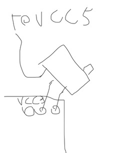
Oh, hey… remember earlier in the thread when I said I thought it was weird that the regulator was referencing vcc3 for the trim pot, pull the trim pot off and reference it to vcc5 and see what happens.

The regulator its self may be feedback looping is my theory.

Why reference the very voltage you are making? That doesn’t sound stable.

Do this with no cpu not in a motherboard. No telling what may happen.

Sphere's PCB projects.
-
Sphere’s socket 5/7 cpu collection.
-
SUCCESSFUL K6-2+ to K6-3+ Full Cache Enable Mod
-
Tyan S1564S to S1564D single to dual processor conversion (also s1563 and s1562)

Reply 574 of 1184, by maxtherabbit

User metadata
Rank l33t
Rank
l33t
pentiumspeed wrote on 2022-12-01, 23:01:

all of this from linear regulator oscillation

Yes I agree, nothing to do with the signals routing

If you can't tame it with caps it's time to use a different regulator

I would shoot for 50mVpp of ripple, if you can get even close to that I'd call it a win. The fact it's working as-is seems to indicate the processor is pretty tolerant of some ripple anyway

Reply 575 of 1184, by feipoa

User metadata
Rank l33t++
Rank
l33t++
Sphere478 wrote on 2022-12-02, 02:33:
Oh, hey… remember earlier in the thread when I said I thought it was weird that the regulator was referencing vcc3 for the trim […]
Show full quote

Oh, hey… remember earlier in the thread when I said I thought it was weird that the regulator was referencing vcc3 for the trim pot, pull the trim pot off and reference it to vcc5 and see what happens.

The regulator its self may be feedback looping is my theory.

Why reference the very voltage you are making? That doesn’t sound stable.

Do this with no cpu not in a motherboard. No telling what may happen.

Could you please draw out in detail what you are suggesting I test. I followed the recommendation presented in the datasheet for this particular VRM.

I plan on checking VCC on my red prototype for the same oscillations. This should offer a good starting point to see if the issue is with the VRM.

EDIT: I was also thinking to remove the trimmer with a fixed resistor to see if trimmer parasitics are causing issues which are not fixed by the bypass on R2.

Plan your life wisely, you'll be dead before you know it.

Reply 576 of 1184, by Sphere478

User metadata
Rank l33t++
Rank
l33t++
feipoa wrote on 2022-12-02, 03:42:
Could you please draw out in detail what you are suggesting I test. I followed the recommendation presented in the datasheet fo […]
Show full quote
Sphere478 wrote on 2022-12-02, 02:33:
Oh, hey… remember earlier in the thread when I said I thought it was weird that the regulator was referencing vcc3 for the trim […]
Show full quote

Oh, hey… remember earlier in the thread when I said I thought it was weird that the regulator was referencing vcc3 for the trim pot, pull the trim pot off and reference it to vcc5 and see what happens.

The regulator its self may be feedback looping is my theory.

Why reference the very voltage you are making? That doesn’t sound stable.

Do this with no cpu not in a motherboard. No telling what may happen.

Could you please draw out in detail what you are suggesting I test. I followed the recommendation presented in the datasheet for this particular VRM.

I plan on checking VCC on my red prototype for the same oscillations. This should offer a good starting point to see if the issue is with the VRM.

EDIT: I was also thinking to remove the trimmer with a fixed resistor to see if trimmer parasitics are causing issues which are not fixed by the bypass on R2.

Basically this.

FF20D7B9-689F-4D28-93C7-410A7DBB221A.jpeg
Filename
FF20D7B9-689F-4D28-93C7-410A7DBB221A.jpeg
File size
35.36 KiB
Views
661 views
File license
Public domain

Do it outside the mobo, no cpu. Might put a load resistor on vcc3 to simulate a cpu load.

I’ve basically convinced myself that this line noise is the regulator at this point.

You can do more tests of course.

But you really should have tried running it from a stable dc source in place of the regulator already it would save you so much guess work. Also, it will tell you the max possible over clock with improved power. You may be maxed out already and this may be pointless cleaning up the power. Though, clean power is nice 😀

If the noise isn’t present it isn’t the regulator. If it is, it is something else

Last edited by Sphere478 on 2022-12-02, 05:14. Edited 2 times in total.

Sphere's PCB projects.
-
Sphere’s socket 5/7 cpu collection.
-
SUCCESSFUL K6-2+ to K6-3+ Full Cache Enable Mod
-
Tyan S1564S to S1564D single to dual processor conversion (also s1563 and s1562)

Reply 577 of 1184, by Sphere478

User metadata
Rank l33t++
Rank
l33t++

Here is powering the cpu externally.

FF45C6BA-DAF5-4D29-B5E0-F7217D5C4213.jpeg
Filename
FF45C6BA-DAF5-4D29-B5E0-F7217D5C4213.jpeg
File size
41.51 KiB
Views
653 views
File license
Public domain

You must check the bench psu doesn’t have live negative. It should be floating or bonded to netural/case/ground.

Some power supplies have a negative that has potential to case/ground/neutral. Don’t use it if this is the case.

Anyway, if the bench psu is any good you may get more overclock. Use your oscilloscope to see how good it is.

I kinda suspect you’ll still be stuck at 80mhz unfortunately. But fingers crossed.

A lithium ion battery source will be the ultimate stable voltage source I’d say. A large AH bank can pretty easily supply 3.7,3.6 etc volts up to 4.2v

Sphere's PCB projects.
-
Sphere’s socket 5/7 cpu collection.
-
SUCCESSFUL K6-2+ to K6-3+ Full Cache Enable Mod
-
Tyan S1564S to S1564D single to dual processor conversion (also s1563 and s1562)

Reply 578 of 1184, by rasz_pl

User metadata
Rank l33t
Rank
l33t
Sphere478 wrote on 2022-12-02, 02:21:

More I ponder this more I think that it is probably the regulator setup its self.
I’ve basically convinced myself that this line noise is the regulator at this point.

Yes, imo 200mV ripple at 800Hz is oscillating regulator. Caps in the middle arent doing anything because they are just stitched to ground and power planes, its like soldering bypass caps on the other side of the board.
Addint small caps could help with high frequency ripple, but that initial low frequency 200mV is a killer and Imo doesnt come from cpu. No amount of signal coupling can have effect on power plane, output buffers being loaded yes, but thats normal switching load.

>Might put a load resistor on vcc3 to simulate a cpu load.
Yes. It would be illumination to see ~2 ohm power resistor (I assume TI486SXL2-66 is consuming 5-10W?) instead of CPU, connected thru couple of CPU socket power pins, not directly to regulator output.
You could also experiment with caps soldered directly on top of output cap. Now that I look at the output cap its also stitched to power plane instead of being between output and load? Where can I download gerbers? - If thats the case desolder regulator, bend output leg out, solder it back, solder wire going from output leg to Cout.

Open Source AT&T Globalyst/NCR/FIC 486-GAC-2 proprietary Cache Module reproduction

Reply 579 of 1184, by feipoa

User metadata
Rank l33t++
Rank
l33t++

I will look at this and do a few more tests over the next few days or weeks. Another thing I could try is adding a 10 or 15 nF cap between the trimmer's terminals.

Keep in mind that I have already tried the Improve-It + Gainbery unit for 90 MHz operation, and it wasn't possible on my best CPU, so the issue with noise here is largely for completeness and understanding.

If you have DIP-14 crystal oscillators in the 81-89 MHz range, we might be able to achieve 85 MHz on some select CPUs, but I don't have any such oscillators and they are (I think) uncommon.

I do have another ultra low drop out regulator with similar pin outs, but will need to be powering a N/C pin. The other unit I have is an LP38503TSX-ADJ. Looking at my notes, the spec sheet for this regulator is using higher value resistors, like 10 K-ohms rather than hundres of ohms for the MIC29302WT. The spec sheet for the LP38503TSX-ADJ sounds more forgiving on capacitor choices. I had tested it before selecting the MIC29302WT.

Looking at my notes from 5 years back,

LP38503TSX-ADJ
0.42V dropout at 3A
Benchtop test at 670 mA resistive load, 3.6V output, 96 mV noise
Vout not constant throughout the 360 mA - 670 mA range

MIC29302WT
0.37V dropout at 3A
Benchtop test at 730 mA resistive load, 3.6V output, 82 mV noise
Vout constant throughout the 360 mA - 730 mA range

From my notes, I did not select the LP38503TSX-ADJ because the output voltage wasn't constant with increasing current. This could mean that running at 2x could result in a 150 mV drop in Vout compraed to 1x mode. On a testbed, and with a resistive load resulting in 360 mA and outputting 3.60 V, increase load to 670 mA, the voltage drops to 3.44 V. This 160 mV drop didn't seem ideal and the MIC29302WT did not suffer from this condition. I also measured lower Vpp noise on MIC29302WT and it has a smaller dropout.

5 years ago, I also tested the LD1085, but my notes indicate the LDO of 1.5 V at 3A, which is not ideal. Also written down were the current tests, simlar to the above. The voltage drop over the 350 mA to 680 mA range was 130 mV. I also noted "gets warmer than 29302".

I did try a 3A switching regulator, LM2596, but the component requirement would increase PCB real-estate and I decided against it.

rasz_pl wrote on 2022-12-02, 06:52:

Yes. It would be illumination to see ~2 ohm power resistor (I assume TI486SXL2-66 is consuming 5-10W?) instead of CPU, connected thru couple of CPU socket power pins, not directly to regulator output.

From my notes, I had used 5 ohm for 670 mA and 10 ohm for 350 mA. I'll have to check what I have, but I could four 20-ohm resistors in parallel between VCC3 and GND pushed into the PGA socket. Or maybe six 30-ohm resistors.

rasz_pl wrote on 2022-12-02, 06:52:

You could also experiment with caps soldered directly on top of output cap. Now that I look at the output cap its also stitched to power plane instead of being between output and load? Where can I download gerbers? - If thats the case desolder regulator, bend output leg out, solder it back, solder wire going from output leg to Cout.

Zip file is here: Re: Custom interposer module for TI486SXL2-66 PGA168 to PGA132 - HELP!
I don't quite follow the suggestion here. I understand 'desolder regulator' and 'bend OUT leg out' so that it doesn't go into the via, then solder the other 4 pins back as normal, and don't solder OUT back to the via? Instead, only connect OUT to the adjacent tantalum with a wire? I could do that. I have a lot to try....

Plan your life wisely, you'll be dead before you know it.