VOGONS


Reply 920 of 1201, by feipoa

User metadata
Rank l33t++
Rank
l33t++
pshipkov wrote on 2023-03-22, 07:26:

Not sure what you mean by “add the pga pins to the top”.

Corrected previous posting to read, "Were you also planning to add the PGA capacitor pins to the top as well?" See my previous photos.

pshipkov wrote on 2023-03-22, 07:26:

The pga132 pins are oriented that way on most adapters i have seen.

Which adaptors were you looking at? I grabbed the first 4 adaptors in my bin and the pins were all oriented the way I installed the PGA pins. The pin widths and lengths were also in agreement with the orientation I selected.

2-Narrow_end_into_socket.JPG
Filename
2-Narrow_end_into_socket.JPG
File size
405.49 KiB
Views
872 views
File license
CC-BY-4.0
3-PGA_direction_adaptor_A.JPG
Filename
3-PGA_direction_adaptor_A.JPG
File size
399.93 KiB
Views
872 views
File license
CC-BY-4.0
4-PGA_direction_adaptor_B.JPG
Filename
4-PGA_direction_adaptor_B.JPG
File size
323.07 KiB
Views
872 views
File license
CC-BY-4.0
5-PGA_direction_adaptor_C.JPG
Filename
5-PGA_direction_adaptor_C.JPG
File size
299.22 KiB
Views
872 views
File license
CC-BY-4.0
6-PGA_direction_adaptor_D.JPG
Filename
6-PGA_direction_adaptor_D.JPG
File size
244.8 KiB
Views
872 views
File license
CC-BY-4.0

Plan your life wisely, you'll be dead before you know it.

Reply 921 of 1201, by feipoa

User metadata
Rank l33t++
Rank
l33t++
pshipkov wrote on 2023-03-22, 07:26:

I dont have cpu removal tools, so your notes a bit ambiguous. But i think i understand what you mean.

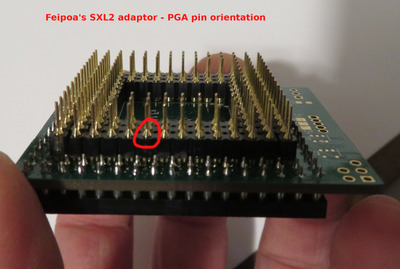
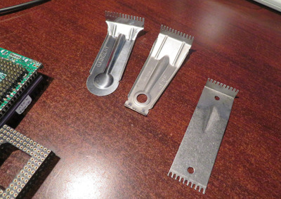
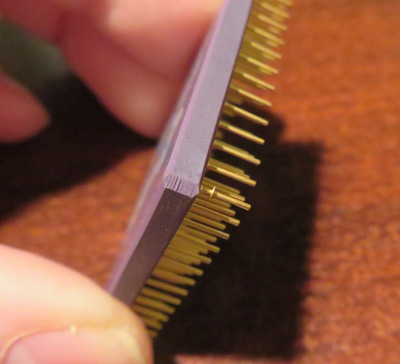
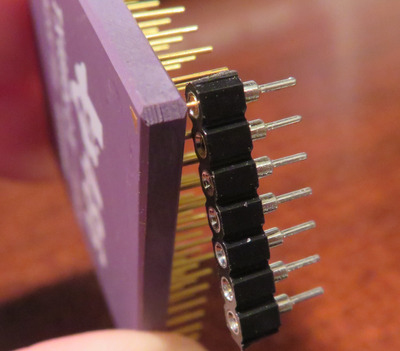
Every PGA CPU removal tool I've seen has looked fairly similar. They were quite common in Cyrix and upgrade adaptor kits. These are mine and this is how they work. I'm showing the SXL2 interposer here:

7b-CPU_removal_tools.JPG
Filename
7b-CPU_removal_tools.JPG
File size
464.7 KiB
Views
871 views
File license
CC-BY-4.0
8-CPU_removal_demo_2.JPG
Filename
8-CPU_removal_demo_2.JPG
File size
255.74 KiB
Views
871 views
File license
CC-BY-4.0
9-CPU_removal_demo_1.JPG
Filename
9-CPU_removal_demo_1.JPG
File size
375.11 KiB
Views
871 views
File license
CC-BY-4.0

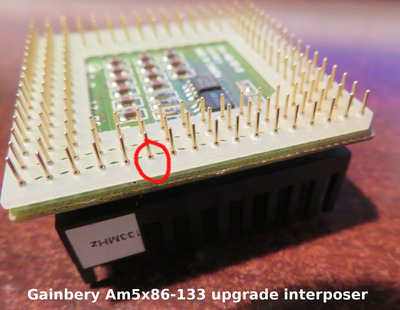
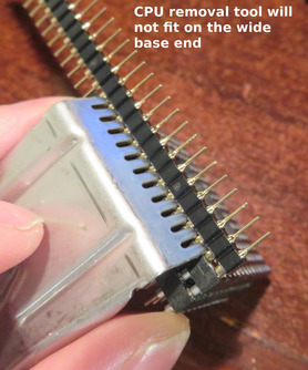
If you install the PGA pins the other direction, no CPU removal tool will fit, as shown:

10-Tool_does_not_fit.JPG
Filename
10-Tool_does_not_fit.JPG
File size
185.29 KiB
Views
871 views
File license
CC-BY-4.0
pshipkov wrote on 2023-03-22, 07:26:

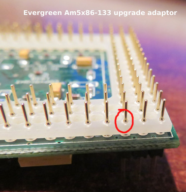
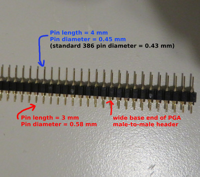
Also, if the pins are oriented that way, insertion and removal is much easier, yet the adapter sits firmly in the socket when inserted.

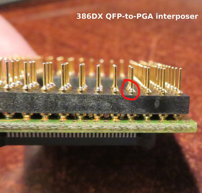
It may fit tight now, but over time and with many removals, you may be widening the female holes on your sockets because the pin diameter on the end you've selected is wider than standard. I have witnessed this first-hand and this was with socket diameters that were only 0.50 mm. You are using 0.58 mm when 0.43 mm is nominal.

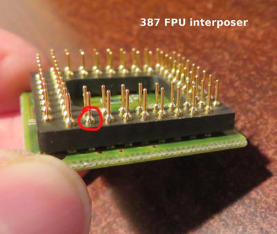
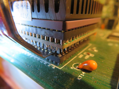
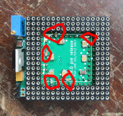
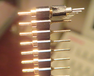
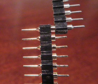
Also, if some of the female pins in the ABS on a socket has a slight inset, your SXL2 adaptor's pins might not snap in. I've run into this on some sockets which had too short of pins. You don't get enough lateral (z-direction) contact area when the pins are too short. See:

7a-header_measurements.JPG
Filename
7a-header_measurements.JPG
File size
592.07 KiB
Views
871 views
File license
CC-BY-4.0
pshipkov wrote on 2023-03-22, 07:26:

Btw, where you measure for noise levels ? Can you confirm, so i do the same here for conformity.

Take measurement right on the VRM pins themselves using low-inductance probe, 10x. There should be photos of this in the thread a few pages back. x-scale: 100 uS, y-scale: 50 mV. Noise: Vp-p, auto measurement feature, or use manual cursor.

pshipkov wrote on 2023-03-22, 07:26:

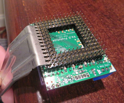
Last note - silk screen on these PCBs can easily crack and chip away.
It requires precise and gentle handling.

As I recall it, the silkscreen on Alpha1 was a bit more robust compared to Alpha2. Perhaps this is where some of the cost cutting went for the JLCPCB discount ($85/batch vs. $2/batch).

Plan your life wisely, you'll be dead before you know it.

Reply 923 of 1201, by ChrisK

User metadata
Rank Member
Rank
Member
maxtherabbit wrote on 2023-03-22, 13:57:

Idk about silk screen, but JLCPCB's solder mask is kinda shitty in general. It flakes off fairly easily

I can confirm that. But it depends on manufacturing lot and/or solder mask color.
I had both good & bad green ones and good black ones so far.

Reply 924 of 1201, by pshipkov

User metadata
Rank Oldbie
Rank
Oldbie

The PGA132 adapters here look like these:
https://i.ebayimg.com/images/g/PTsAAOSwiLVf3hPq/s-l500.jpg
https://i.ebayimg.com/images/g/uJoAAOSwHb9brlqI/s-l1600.jpg

So you can see why i considered the orientation of the pins the way it is on the shared photos.
But that was only the initial consideration.
Once i tested the two sides of the pins by inserting them in the socket it became obvious that the winning configuration is the one i ended up doing.
Feipoa, if you have remaining pins, put them in a PGA132 adapter and then insert them in a CPU socket. You will see what i mean by "easy to handle, yet sturdy".
But, yeah, i never used these removal tools, so they were not a factor i considered.

Found the pictures of where you measured. Thanks for the notes.
Those capacitors on the top are still in transit to here.

Good to know others have similar issues with the JLCPCB surface cover.
Well, it is not good really, but you know what i mean.

retro bits and bytes

Reply 925 of 1201, by feipoa

User metadata
Rank l33t++
Rank
l33t++
pshipkov wrote on 2023-03-22, 16:43:
The PGA132 adapters here look like these: https://i.ebayimg.com/images/g/PTsAAOSwiLVf3hPq/s-l500.jpg https://i.ebayimg.com/image […]
Show full quote

The PGA132 adapters here look like these:
https://i.ebayimg.com/images/g/PTsAAOSwiLVf3hPq/s-l500.jpg
https://i.ebayimg.com/images/g/uJoAAOSwHb9brlqI/s-l1600.jpg

So you can see why i considered the orientation of the pins the way it is on the shared photos.

Sorry, I just don't follow. I must be missing something fundamental. You are showing sockets, I am showing full CPU adaptors. We are creating CPU adaptors.

pshipkov wrote on 2023-03-22, 16:43:

Once i tested the two sides of the pins by inserting them in the socket it became obvious that the winning configuration is the one i ended up doing.

Hmmm, I still don't follow. I also tested both sides of the pin and found the winning orientation to be the one I selected. I have shared my 3 reasons, but I'm not seeing your reasoning. I want to understand your choice, but I don't. Am I the only one here not to follow?

pshipkov wrote on 2023-03-22, 16:43:

Feipoa, if you have remaining pins, put them in a PGA132 adapter and then insert them in a CPU socket. You will see what i mean by "easy to handle, yet sturdy".

Yes I haves ome remaining pins - you can them in the last photo I shared above w/measurements. I have inserted them all sorts of ways and if I plug them into a socket, they are just barely seated with your orientation. The pins need to be longer for this orientation to be robust. The male pins definitely do not reach the bottom of the mating female socket. You want to feel the pins to click in to the socket, then continue to move down some.

pshipkov wrote on 2023-03-22, 16:43:

But, yeah, i never used these removal tools, so they were not a factor i considered.

Even if I didn't have a removal tool, I would still orient the pins as I've shown, for reasons of pin length, pin width, and consistency with other CPU adaptors. I am trying to understand your reasons, but there must be something wrong with my brain today because I cannot see any reason to install them as you have. I want to understand, not be argumentative. Is it that you prefer this orientation because the pins fit a bit tighter into the motherboard - although they barely click-in and will widen the holes?

pshipkov wrote on 2023-03-22, 16:43:

Those capacitors on the top are still in transit to here.

But I saw you shared a photo with these same caps soldered onto the bottom of the PCB. They are the same caps for the top PGA pins. Did you order too low a quantity? I'm not referring to the 1210 caps.

PGA_Vin_caps_top_options.JPG
Filename
PGA_Vin_caps_top_options.JPG
File size
344.41 KiB
Views
821 views
File license
CC-BY-4.0
pshipkov wrote on 2023-03-22, 16:43:

Good to know others have similar issues with the JLCPCB surface cover.

Roll the dice.

Plan your life wisely, you'll be dead before you know it.

Reply 926 of 1201, by pshipkov

User metadata
Rank Oldbie
Rank
Oldbie

Ok, let me try to elaborate in more detail.

I always put PGA132 sockets on 386 class CPUs / adapters.
Otherwise their (CPUs/adapters) pins get janky over time. I am handling them carefully, but one way or another wear and tear happens.
If i have a socket on them, the socket gets the beating and is easy to replace at any point. Condition of CPU/adapter pins gets preserved.

Because of the above practice i noticed that these PGA132 sockets are actually much better to handle than the longer pins of the CPUs.
They snug tightly in the motherboard's CPU/FPU sockets, yet are much easier to separate when needed.
With all the testing that i am doing this is a VERY big factor, so naturally that experience and thinking led to my decision about pins orientation.
It is entirely based on practicality.

Hope these notes make it more clear.

About capacitors on the top.
I thought you are asking about the big ones, but my note applies to the small ones as well.
That order is still on its way here.
I scavenged some broken components for the same type of capacitors. Managed to obtain enough for the bottom, but not enough for the top.
The order is about to arrive today or tomorrow.
Will wait for it instead of searching the pile of rust for the right caps.

retro bits and bytes

Reply 927 of 1201, by feipoa

User metadata
Rank l33t++
Rank
l33t++
pshipkov wrote on 2023-03-22, 18:09:

I always put PGA132 sockets on 386 class CPUs / adapters.

I always put PGA132 sockets on 386 class CPUs / adapters.

This was the missing information. I didn't see you mention this earlier - did I miss it, or did you not mention it?

If you are placing the SXL2 unit into "disposable" intermediary sockets, then using your selected orientation doesn't matter so much. I am not using such sockets with these.

Were you able to find gold-on-gold PGA132 sockets? Ideally, you would want to use gold-female, gold-male 132 sockets for this to avoid dissimilar metal corrosion or loss of conductivity. Gold on gold are very hard to find though, so if you have a source, could you PM me the details.

I think I have only 4x PGA168 gold on gold and 2x PGA132 gold on gold.

Plan your life wisely, you'll be dead before you know it.

Reply 928 of 1201, by pshipkov

User metadata
Rank Oldbie
Rank
Oldbie

No, you didn't miss it.
I didn't communicate it. : )

I already made my point, but one last set of notes, for clarity.
The orientation of the pins fit well both intermediary and motherboard sockets. They are the same thing really.
The shorter length + wider base makes this side of the pins much more resistant to bending/breaking.
Combined with the easier insertion/removal (less force needed because of shorter pins) i felt that i can actually go without intermediary socket for these adapters.

All my PGA132 sockets have white metal pins that looks quite cheap.

retro bits and bytes

Reply 929 of 1201, by feipoa

User metadata
Rank l33t++
Rank
l33t++

Yeah but total contact surface area is reduced and you will, overtime, regret this as your female holes widen.

Get yourself a CPU removal tool. Saves a lot of effort, saves the sockets, saves the pins - no more prying on ABS with flatheads for those tighter fittings, no more yanking at an angle, etc. I thought this was rubbish until I got one myself, now I won't do without it, kind of like the first time I tried solder paste, I cannot go back.

Plan your life wisely, you'll be dead before you know it.

Reply 930 of 1201, by pshipkov

User metadata
Rank Oldbie
Rank
Oldbie

Since you brought the point early, i asked myself why didn't get one of these tools. No good explanation.

The two adapters are in place now, so no way going back.
But may make a third one eventually, but that will be at unspecified later time. Ran out of components already.

retro bits and bytes

Reply 931 of 1201, by pentiumspeed

User metadata
Rank l33t
Rank
l33t
feipoa wrote on 2023-03-22, 19:51:

Yeah but total contact surface area is reduced and you will, overtime, regret this as your female holes widen.

Get yourself a CPU removal tool. Saves a lot of effort, saves the sockets, saves the pins - no more prying on ABS with flatheads for those tighter fittings, no more yanking at an angle, etc. I thought this was rubbish until I got one myself, now I won't do without it, kind of like the first time I tried solder paste, I cannot go back.

Having trouble finding this removal tool on ebay. Suggestions?

Yes I had one, now I need one.

Cheers,

Great Northern aka Canada.

Reply 932 of 1201, by feipoa

User metadata
Rank l33t++
Rank
l33t++

I'm not sure where to buy them these days, but the best one is the Cyrix branded unit. If you look at my photo of 3 removal tools above, the one on the far right is preferred because it has two slot sizes on either end of the pry bar. The end with the wider slots can even fit between the fatter nubs on sockets, so if you stack sockets, you can still separate them with this tool. I think it came in Cyrix 386 upgrade kits, so if you see a boxed set online (e.g. DRx2, DLC), it is probably in there if the seller hasn't lost it.

The removal tool on the far left is from a Gainbery 5x86 upgrade box. Those were fairly plentiful. However, it doesn't have the wider slot widths.

Plan your life wisely, you'll be dead before you know it.

Reply 933 of 1201, by maxtherabbit

User metadata
Rank l33t
Rank
l33t
pentiumspeed wrote on 2023-03-22, 20:57:
Having trouble finding this removal tool on ebay. Suggestions? […]
Show full quote
feipoa wrote on 2023-03-22, 19:51:

Yeah but total contact surface area is reduced and you will, overtime, regret this as your female holes widen.

Get yourself a CPU removal tool. Saves a lot of effort, saves the sockets, saves the pins - no more prying on ABS with flatheads for those tighter fittings, no more yanking at an angle, etc. I thought this was rubbish until I got one myself, now I won't do without it, kind of like the first time I tried solder paste, I cannot go back.

Having trouble finding this removal tool on ebay. Suggestions?

Yes I had one, now I need one.

Cheers,

I've been fruitlessly searching for one since an LGR video made me aware of their existence

Reply 934 of 1201, by pshipkov

User metadata
Rank Oldbie
Rank
Oldbie

Somebody watching this thread forwarded a diagram from the Am386 datasheet, page 138:

1.jpg
Filename
1.jpg
File size
72.69 KiB
Views
703 views
File license
Public domain

Also, difference between short/long side pins is 1mm - for the record.

retro bits and bytes

Reply 935 of 1201, by rasz_pl

User metadata
Rank l33t
Rank
l33t

>Having trouble finding this removal tool on ebay. Suggestions?

why not make one? CNC router and some Steel Flat Stock, maybe even laser nowadays

Open Source AT&T Globalyst/NCR/FIC 486-GAC-2 proprietary Cache Module reproduction

Reply 936 of 1201, by feipoa

User metadata
Rank l33t++
Rank
l33t++
rasz_pl wrote on 2023-03-23, 05:45:

>Having trouble finding this removal tool on ebay. Suggestions?

why not make one? CNC router and some Steel Flat Stock, maybe even laser nowadays

I think there's a limit to how far the typical computer hobbiest will go. Are you offering your service?

pshipkov wrote on 2023-03-23, 05:24:

Somebody watching this thread forwarded a diagram from the Am386 datasheet, page 138:

1.jpg

Also, difference between short/long side pins is 1mm - for the record.

Nice image. I've been doing my measurements off of actual samples. I see the units are in (ugh) inches. Converting them, it is showing the pin diameter to be between 0.41 - 0.51 mm. I measured 0.43 mm on several 386 CPUs. The diagram is also showing pin length, up to the stopper knub, to be between 2.7 - 3.2 mm. However, the stopper knub fits into the female parts, as shown on this 486DLC:

IMG_2123.JPG
Filename
IMG_2123.JPG
File size
1.12 MiB
Views
685 views
File license
CC-BY-4.0
IMG_2124.JPG
Filename
IMG_2124.JPG
File size
938.88 KiB
Views
685 views
File license
CC-BY-4.0

I measured the distance from the stopper knub to the end of the pin to be 3.4 mm.
Similarly, the longer pins on the row headers with the pyramidal ends fit snugly into the PGA orifice:

IMG_2126.JPG
Filename
IMG_2126.JPG
File size
433.1 KiB
Views
685 views
File license
CC-BY-4.0

Contrary to the fat ends:

IMG_2128.JPG
Filename
IMG_2128.JPG
File size
750.54 KiB
Views
685 views
File license
CC-BY-4.0

By the way, these single male-female row headers I'm showing in these images are particularly lousy. They get stretched out almost immediately by those fatter ends. Actual PGA sockets, on the other hand, appear a bit more robust.

Plan your life wisely, you'll be dead before you know it.

Reply 937 of 1201, by rasz_pl

User metadata
Rank l33t
Rank
l33t
feipoa wrote on 2023-03-23, 06:12:
rasz_pl wrote on 2023-03-23, 05:45:

>Having trouble finding this removal tool on ebay. Suggestions?

why not make one? CNC router and some Steel Flat Stock, maybe even laser nowadays

I think there's a limit to how far the typical computer hobbiest will go. Are you offering your service?

in US:
https://www.oshcut.com afaik from oshpark guys
cheaper - Starting from $29 https://sendcutsend.com/materials/1075-blue-t … r-spring-steel/ https://www.practicalmachinist.com/forum/thre … tch-out.379025/
Im sure if not jlcpcb then some other Chinese vendor is offering same service even cheaper.

Open Source AT&T Globalyst/NCR/FIC 486-GAC-2 proprietary Cache Module reproduction