Reply 1121 of 1184, by PC Hoarder Patrol

Rank
l33t
- Rank
- l33t
rasz_pl wrote on 2024-03-20, 17:42:Sphere478 wrote on 2024-03-20, 14:49:Saw this, haven’t dug too deep, anyone know what the extra circuit is?
I think I saw same cpu + weird interposer on os2museum long time ago
386 Cache Coherency - https://www.os2museum.com/wp/386-cache-coherency/
Reply 1122 of 1184, by rasz_pl
Rank
l33t
PC Hoarder Patrol wrote on 2024-03-20, 21:21:rasz_pl wrote on 2024-03-20, 17:42:Sphere478 wrote on 2024-03-20, 14:49:Saw this, haven’t dug too deep, anyone know what the extra circuit is?
I think I saw same cpu + weird interposer on os2museum long time ago
386 Cache Coherency - https://www.os2museum.com/wp/386-cache-coherency/
Mystery Gadget! 😀 thank you for precise link
Reply 1123 of 1184, by feipoa

Rank
l33t++
- Rank
- l33t++
I think user Anonymous Coward mentioned having one of these at one point in time. I know another user here who bought one recently for, I think, $85, but I haven't heard from him in 6 months. There is one of these on eBay right now for an absurd price. There were also PGA132 plug-in/stacked cache coherency interposers. I have one, but have never needed it on any motherboard I've tested. I'm setting up my SXL2-90 system right now and I don't appear to need any additional coherency adaption.
Plan your life wisely, you'll be dead before you know it.
Reply 1124 of 1184, by RayeR
Rank
Oldbie
- Rank
- Oldbie
Thanks for the link to OS2M article that explains cache coherency problems and solutions but it still didn't explain how this folded circuit works, why there's an oscillator and ripple counter. In discussion someone guess that it may perform as some presice delay circuit for timing some signal. Maybe... If someone have this CPU in hands why not to beep the connections with DMM and draw a schematic? It's a simple circuit to reverse. Then we would know more...
Gigabyte GA-P67-DS3-B3, Core i7-2600K @4,5GHz, 8GB DDR3, 128GB SSD, GTX970(GF7900GT), SB Audigy + YMF724F + DreamBlaster combo + LPC2ISA
Reply 1125 of 1184, by feipoa
Rank
l33t++
- Rank
- l33t++
I checked my Evergreen stand-alone, PGA-132 plug-in interposer, which adds some flush circuit, but it uses a PAL.
I then checked my Evergreen SXL2-66 QFP, but it also uses a PAL: download/file.php?id=43319&mode=view
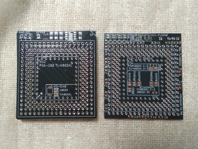
However, I do have an Improve-It PGA168 to PGA132 interposer which uses the same parts as that unsightly dingus, namely 74HC4024AD, 74VHC00, and 6.00X. It was shown previously in this thread here: download/file.php?id=48960&mode=view
I haven't had the need for a discrete flush circuit. I think user MikeSG was already planning to produce an interposer with several compatibility options for those uncommon cases. I can trace it out if he thinks he wants to include it. For me personally, I wonder if these extra flush circuit components may hinder overclock ability. We are already up to 90 MHz without any of these parts. I had to run it at 5 V to get to 90 MHz though.
Plan your life wisely, you'll be dead before you know it.
Reply 1126 of 1184, by MikeSG
Rank
Member
The only connections I can see on the folded/flexible circuit to the CPU are Flush, HLDA, VCC, GND... HLDA can be used with MEMW to activate Flush, but it seems to be doing it without MEMW. After a certain amount of clocks has passed while HLDA is active, Flush is activated? Not exactly sure.
On the interposer I designed, IC1-FLUSH takes HLDA + MEMW (or M/IO and SO) to activate Flush. ... Or,"MEMW#" the large single pin header on top connects to the TI486SXL's MEMW pin, which activates flush.... Or, you can not use either of those and use the Cyrix utility to activate BARB, which activates Flush on each HLDA.
The flexible circuit with ripple counter does seem to be the better way to suit all types of boards, though. If I need to do a redesign it may be better to do it that way.
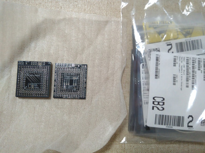
The parts for my design came in the mail in the last few days, just need to wait ~a month for the sockets.
Attachments
Reply 1127 of 1184, by feipoa
Rank
l33t++
- Rank
- l33t++
MikeSG:
I like how the 100 nF caps have dedicated pads. It looks better than the suspended 0805 caps on my unit, and is easier to solder.
What is the primary reason you don't want to solder on on all PGA pins (168 + 132)? You have been waiting quite some time for these specialised press-fit PGA units. I just assembled another interposer yesterday to serve as a straight 5V only adaptor. The time required for soldering all 168 + 132 pins by hand was 4 hours. I can see how this may not be ideal for mass assembly. Do you plan on assembling quite a large number, thus not wanting to solder all these pins?
When I clicked on those mouser links for the PGA pins/sockets you are using, they come up at about $50 and $55. Is that for all 2-dozen or so units, or is that per piece? If per-piece, wow! Spare no expense.
I take it that you do you not want the Improve-It flush circuit traced out at this time?
EDIT: The traces on the Improve-It dongle are pretty clear on the eBay photo. I don't think I'd be able to improve on it any.
Plan your life wisely, you'll be dead before you know it.
Reply 1128 of 1184, by kingcake

Rank
Oldbie
- Rank
- Oldbie
Sphere478 wrote on 2023-12-31, 17:11:Very interesting! Love it! Especially the ambition for other chips! […]
Very interesting! Love it! Especially the ambition for other chips!
Interesting choice for regulator. 1.5a? Looks like. Little small🤔 at 3.6v that’s a max wattage of 5.4w I don’t recall the TDP of chips in question, but isn’t it right around 5w? 5v chips of course are direct wire, no reg.
I double dare you to get a POD running on this! :p
Fingers crossed!
His design will not be able to sustain that wattage. The thermal pad is too small and not stitched to multiple layers.
Reply 1129 of 1184, by MikeSG
Rank
Member
There's smaller versions of the LDO regulator I'm using that are still rated for the same spec. The solder/thermal pad is connected to the entire top layer and stitched with 18 nearby vias to the central large GND plane, and bottom layer. This is the datasheet (in SO-8EP): https://www.diodes.com/assets/Datasheets/AP7363.pdf
About the caps, the 100nf/0.1uf caps share one or two VCC pins each, the top six VCC pins have no 0.1uf caps but are close to one central 0.1uf and the three 3.3uf caps. I made a mistake though, the vias next to the 0.1uf pads (side & bottom caps) don't do anything because the VCC & GND pins on the socket connect straight through to VCC & GND anyway. VCC is supposed to come through the twin vias then past the cap to the VCC pin. Your design is probably better for noise but I just wanted it to be neat.
Soldering all the PGA-132 pins in rows in a specific order, trying to work out how to solder both top & bottom sockets by hand I don't want to do... Yes both the PGA-132pin and the PGA-168pin press fit are ~$50 AUD/CAD each, or ~$33 USD each.
I don't know how mass producible it is... the sockets total $100... the rest of the components are cheap though. Maybe another $50 for PCB + other parts. For one interposer. If it works I'll build left-overs or "build it yourself" kits and put them on eBay. How many people are actually looking for a solution?
The Improve-It circuit is clear, thanks.
Reply 1130 of 1184, by ChrisXF

Rank
Newbie
- Rank
- Newbie
I don't know if anyone has provided any formal guidance on how the original feipoa interposer should be assembled? I was guessing when I did it a strip at a time, working outwards.
Reply 1131 of 1184, by feipoa
Rank
l33t++
- Rank
- l33t++
@MikeSG
Looking forward to seeing your working unit. The press-fit PGA units certainly add some character, but too pricey for me.
@ChrisXF
I ceased working on the assembly guide. It didn't seem like there was much interest. There's a certain order you must adhere to in order to solder the 300 PGA pins. It should be relatively simple to assemble if you have moderate soldering skills. No solder paste needed. Today I assembled another unit and the pins only took 3 hours this time.
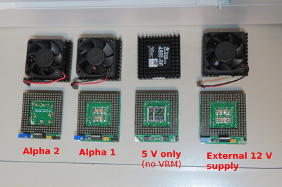
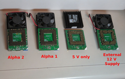
The reason I've been assembling more units is due to working on my SXL2-90 build. I determined that 4.95 V wasn't quite sufficient for running Windows at 90 MHz. Thus, I first assembled an interposer that has no regulator on board, that is, it uses 5V straight from the PSU. I simply bridged Vin and Vout. I did this in 4 locations. You may noticed the oversized tantalum caps which barely fit on the pads. I had these in my bin and realised I'd never use them otherwise. Unit tested working.
From these tests, I realised I needed 5.10 - 5.15 V to get 90 MHz stable. I determined this because I pulled out a PSU which outputs a little high on the 5 V rail. However, that PSU is specifically for another of my systems and I cannot swap them permanently.
Scratching my head, I was wondering how to get more voltage to my SXL2. I came up with a few solutions, but decided that the quickest means was to assemble another interposer unit which used 12 V from the PSU, then down regulate from there. Looking at the spec sheet for LP38503TS-ADJ and LP38501TS-ADJ, it was noted that Vin should not exceed 5.5 V, meaning I could not safely use 12 V from the PSU.
Next, I looked at the spec sheet for MIC29302WT, and it stated that the maximum continuous input voltage can be 26 V. We're in business. Note that MIC29302WT was the original VRM originally spec'd for this project.
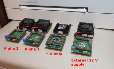
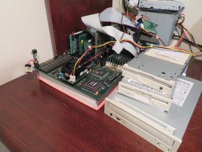
To use 12 V from the PSU, I had to pull out all the PGA pin which supplied 5 V from the motherboard's PGA socket. Rather than pulling out these 20 pins, I simply assembled another interposer without the pins. Then, connect the 12 V molex to the +Fan terminal on the interposer. This Fan+ now serves as Vin to MIC29302WT. I loose the ability to connect the fan directly to the interposer, but that's the way it goes sometimes. See photos.
I decided not to solder on the -Fan (GND) header, although this would make the molex connector hold better. Connecting molex to GND on the interposer would create a ground loop. Anyone think this ground loop would be problematic? I may connect it just for molex stability.
Plan your life wisely, you'll be dead before you know it.
Reply 1132 of 1184, by MikeSG
Rank
Member
Looking good.
Is the fan normally on the interposer 5V? They put out quite a lot of noise.
I don't think which ground matters, may be slightly cleaner using the PSU/molex ground. Modern GPUs and CPUs have their own independant power going to the PSU.... I thnk when you use multiple AC-DC converters then you can create a ground loop...
Reply 1133 of 1184, by Paralel
Rank
Member
To get to 90, are you still using clock doubling, so the external clock has been raised from 33 to 45, or is the external clock still 33 and you altered the multiplier? Is your goal to get to 99/100 so it is "clock tripled"?
Reply 1134 of 1184, by Sphere478

Rank
l33t++
- Rank
- l33t++
kingcake wrote on 2024-03-25, 18:59:Sphere478 wrote on 2023-12-31, 17:11:Very interesting! Love it! Especially the ambition for other chips! […]
Very interesting! Love it! Especially the ambition for other chips!
Interesting choice for regulator. 1.5a? Looks like. Little small🤔 at 3.6v that’s a max wattage of 5.4w I don’t recall the TDP of chips in question, but isn’t it right around 5w? 5v chips of course are direct wire, no reg.
I double dare you to get a POD running on this! :p
Fingers crossed!His design will not be able to sustain that wattage. The thermal pad is too small and not stitched to multiple layers.
Yeah, I had the same concern. They seem confident though, let’s see what testing shows.
@feiopa, if you use a longer fan pins you can bend them 90 degrees out the bottom and connect to it down there and still install a fan
You should run ground and 12v in parallel from the tap location to the source. This is important. You can create issues if you don’t.
By the way, I designed the power layer to have its source from the regulator pad. Results may be better from that location if you can tap that.
Reconfiguring it for 12v should be fine, good idea 😀 so long as you did your homework, and remove the motherboard 5v pins as you noted. I can’t think of a reason why that would be an issue. Good job. But backfeeding the fan header may not be ideal. The arrangement of the pin header that you wanted limited the current that header can handle. And the input capacitor is close to the regulator pad, not the fan header. Btw, be sure the input capacitors are good for 12v and different values may be ideal when using 12v
Reply 1135 of 1184, by kingcake
Rank
Oldbie
- Rank
- Oldbie
Sphere478 wrote on 2024-03-26, 18:06:kingcake wrote on 2024-03-25, 18:59:Sphere478 wrote on 2023-12-31, 17:11:Very interesting! Love it! Especially the ambition for other chips! […]
Very interesting! Love it! Especially the ambition for other chips!
Interesting choice for regulator. 1.5a? Looks like. Little small🤔 at 3.6v that’s a max wattage of 5.4w I don’t recall the TDP of chips in question, but isn’t it right around 5w? 5v chips of course are direct wire, no reg.
I double dare you to get a POD running on this! :p
Fingers crossed!His design will not be able to sustain that wattage. The thermal pad is too small and not stitched to multiple layers.
Yeah, I had the same concern. They seem confident though, let’s see what testing shows.
Unless I'm not seeing something in the pics, there's just not enough copper there. If I had to guess, just 1 watt of dissipation will make that thing climb to 70+ degrees Celsius in a few minutes. That would barely support 500mA at a 5V -> 3V drop.
No need to rely on empirical testing. All the math you need for copper area and thermal resistance are in the datasheet.
Reply 1136 of 1184, by feipoa
Rank
l33t++
- Rank
- l33t++
Thanks for the comments.
The probability of MikeSG's interposer working with a POD is very low, so the discussion as to whether the thermal pad for the SMD regulator is sufficient seems pretty mute. Or am I missing something? MikeSG mentioned he'd consider a different interposer for DX4+ chips. Maybe the comments here are directed toward his next potential iteration.
MikeSG:
Yes, the fan is normally connected to the interposer for the case that there's 5V into the VRM and 3.6V out. The fan normally connects to the 5V in, not to 3.6V out. I don't recall noting any issues with noise with the fan connected or disconnected when doing noise comparisons on the scope. In either case, one can elect to connect the fan directly to the PSU if desired.
Paralel:
I'm using a 90 MHz crystal oscillator plugged into the motherboard. It's a standard off-the-shelf part. 90 MHz oscillators provide 45 MHz FSB. SXL2 clock doubles this, so 90 MHz internal to the CPU. We had some discussion previously on the frequency profile of these DIP crystal oscillators. FFT showed both 45 and 90 MHz on the scope. It isn't clear to me if the SXL is simply not halving the incoming frequency for clock-doubled mode. There was some other discussion on this, but the details escape me.
Sphere478:
Your comment to check the tantalum's input voltage rating was sound. When I first read your comment, I was thinking I had a 10 V tantalum on there. I checked the datasheet, and it was 16 V. Had I used the 47 uF tantalum, that would have been only 10 V.
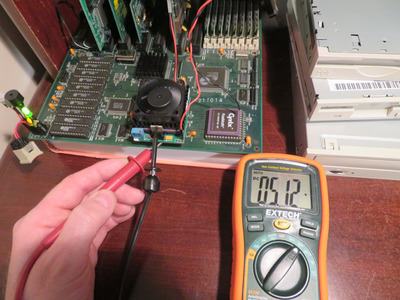
I am not too concerned with the headers right now. They are rated for 3 A. When I measure the current going through it, I see 2.0 A, and that is going through nearly 3 metres of cable, so probably a bit less than 2 A hooked up to the molex (no DMM, no extra clips). My original plan was to solder an 18 gauge wire directly from the PSU's 12V rail to the interposer, but decided I'd test with the molex connector first. The molex connector is substantially more tighly connected compared to black connector I showed in one of the photos. I can see a lot of extra current being required to pass that style of female connection.
Yes, I can bridge off the connector and also connect a fan, but it would need to be a 12 V fan. I'm currently using 5 V fans. I'm OK using the PSU for fan connect right now. Finer tuning will come after I determine I can get stable 90 MHz operation in NT 3.51 and win 3.11.
I plan on soldering on an isolated mini molex to the PSU and a spare 18 AWG wire before I do more testing. Try to do some rough estimates based on how hot the VRM gets on the IR gun to see if I'm loosing too much to the header itself, then switch to a soldered 18 AWG cable.
Good point about graphic cards taking in ground from the molex as well. I've already connected the second ground path.
I find the VRM heating up quite a bit with 12 Vin, whereas it doesn't even get warm with 5 Vin. I'll need to be screwing the VRM to the heatsink for this round of testing.
Plan your life wisely, you'll be dead before you know it.
Reply 1137 of 1184, by Sphere478
Rank
l33t++
- Rank
- l33t++
Yes, the larger the voltage change, the less efficient the conversion will be. I see this effect in solar charge controllers. You ideally want a input just a little bit above your maximum regulation voltage. I still like your 12v idea though. Too bad 7v isn’t an option.
Your total wattage is your loads plus your losses. In this case moving to 12v will put less load (amperage) on the 12v side, but over all wattage will be higher because of conversion losses
I was speaking to the regulator seeming small for any 486 chip in my mind let alone a POD, but I will defer to the creator as they have looked into the matter more than I, and I await their results.
I was trying to say, internally in the PCB the power connections to the fan header are weak, and not near the input capacitor. It is far better to connect power input to the regulator pads for power input. But at least it’s 12v and the amps will be lower than 5v edit: looked at fan connections again in previous post, they aren’t as good as the regulator pad but not as bad as I was remembering. Still suggest moving the wires, but I’m a little less worried now.
Reply 1138 of 1184, by H3nrik V!
Rank
Oldbie
- Rank
- Oldbie
Sphere478 wrote on 2024-03-27, 05:47:I was trying to say, internally in the PCB the power connections to the fan header are weak, and not near the input capacitor. It is far better to connect power input to the regulator pads for power input. But at least it’s 12v and the amps will be lower than 5v edit: looked at fan connections again in previous post, they aren’t as good as the regulator pad but not as bad as I was remembering. Still suggest moving the wires, but I’m a little less worried now.
Unfortunately not. A linear/LDO regulator does not work in "Watts in -> Watts out". If output current is 2 Amps, input current is 2 Amps (plus whatever is required for regulation - mostly neglible). So the Watts dissipated in the regulator increases a lot.
Please use the "quote" option if asking questions to what I write - it will really up the chances of me noticing 😀
Reply 1139 of 1184, by H3nrik V!
Rank
Oldbie
- Rank
- Oldbie
feipoa wrote on 2024-03-27, 04:34:I am not too concerned with the headers right now. They are rated for 3 A. When I measure the current going through it, I see 2.0 A, and that is going through nearly 3 metres of cable, so probably a bit less than 2 A hooked up to the molex (no DMM, no extra clips). My original plan was to solder an 18 gauge wire directly from the PSU's 12V rail to the interposer, but decided I'd test with the molex connector first. The molex connector is substantially more tighly connected compared to black connector I showed in one of the photos. I can see a lot of extra current being required to pass that style of female connection.
Assuming you are measuring in series with the nearly 3 metres of cable? Then the current will be 2.0A no matter what. Voltage may be a little lower in the sink end of the wire than the source end, though.
Please use the "quote" option if asking questions to what I write - it will really up the chances of me noticing 😀