VOGONS


Reply 1140 of 1184, by MikeSG

User metadata
Rank Member
Rank
Member

PODs take 5V in, why use a regulator at all...

I still don't see a problem with my VR design... For a 3.3v 1Amp (typical worst case) CPU draw, the datasheet says Power Dissipation required is 1.7W, Max Power Dissipation possible for the SO-8EP package to the copper area is 2.36W (25C day), and 2.0W (40C day). Copper area is multiple times larger than a 1cm x 1cm standing VR with a heatsink and/or the VR on the POD itself which gets hot with the CPU.....

Reply 1142 of 1184, by feipoa

User metadata
Rank l33t++
Rank
l33t++

[EDIT: I'm not talking about the POD here. Adding this to not confuse some readers]

My primary concern moving forward is going to be dissipating all this heat while not exceeding the VRM's junction temperate rating. Assuming the 2A value is correct, rough calculations indicate about 12 W minimum I need to dissipate, which places the junction temp at 125 C. Ideally, I think I'd want to be below that temperature. I've already added a heatsink to the VRM and attached the VRM to the SXL heatsink, however I may need a larger fan and primary heatsink.

Maybe I can add a few parallel power resistors to the 12 V feed to not put so much burden on the VRM? That is, get Vin down to 8 V.

Plan your life wisely, you'll be dead before you know it.

Reply 1143 of 1184, by H3nrik V!

User metadata
Rank Oldbie
Rank
Oldbie
feipoa wrote on 2024-03-27, 07:41:

Maybe I can add a few parallel power resistors to the 12 V feed to not put so much burden on the VRM? That is, get Vin down to 8 V.

If you know your maximum current draw, yes, that is an option. The resistors, of course would dissipate the power and get hot then.

At 2 amps, you'd need (12V-8V) /2A = 2 Ohms. Power dissipation of the resistors would be (12V-8V)*2A = 4Watt and you would want some overhead to that 😀 (I think I'd go with at least 10W of capability)

Please use the "quote" option if asking questions to what I write - it will really up the chances of me noticing 😀

Reply 1145 of 1184, by feipoa

User metadata
Rank l33t++
Rank
l33t++

The diode, like the parallel resistors, will also heat up. Either the VRM's heatsink dissipates the heat, or some inline component does. I should have some 6 A diodes though.

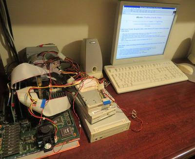
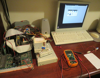
I ran several tests yesterday and have reached success. I'll report on it in more detail after I run more extensive tests.

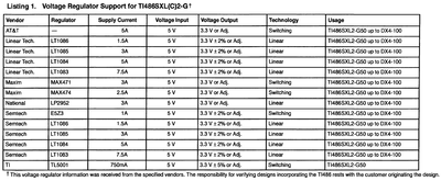
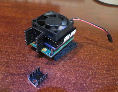
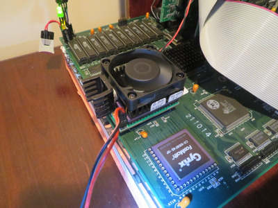
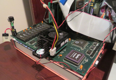
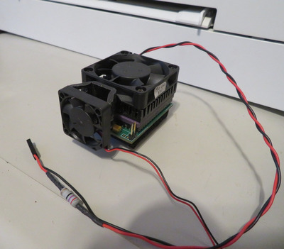
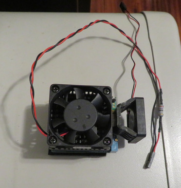
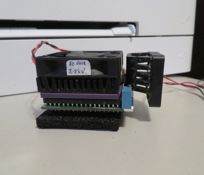
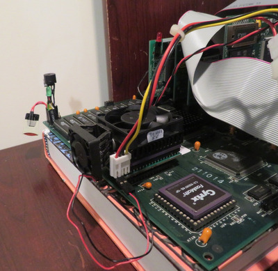
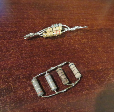
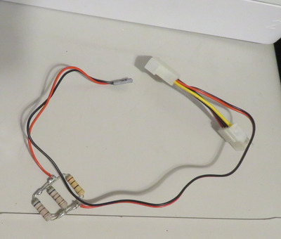
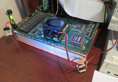
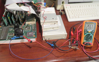
By the way, I calculate the current going into the VRM as 1.03 A. I added a heatsink to the VRM and a larger fan to the CPU's heatsink. I've also added a 25 mm fan to the VRM's heatsink. I did add some 2W parallel resistors to drop 2 V . However, over the course of 6 minutes running, that voltage drop increased to 2.5 V, further heating up the resistors. I recorded 63 C on one of the resistors and decided adding a small fan to the VRM's heatsink is better than having inline components.

@Mike, yes, a switching regulator may be better, however I don't think there is any plug-in, pin-compatible, switching regulator that wouldn't require a PCB redesign. With the original spec, from 5.0 Vin to 3.6 Vout, a linear LDO doesn't even get warm. What I am doing now is an after thought, one I never thought would be doing. I don't think anyone else is going to attempt more than 5 V on one of these SXL2 CPUs.

It does beg the question, though - with a peltier and a large copper socket 370 heatsink, can I get 100 MHz out of an SXL2? And at what voltage? Would going too far over, say 5.5 V, start to irritate the northbridge?

Plan your life wisely, you'll be dead before you know it.

Reply 1146 of 1184, by Sphere478

User metadata
Rank l33t++
Rank
l33t++
H3nrik V! wrote on 2024-03-27, 07:04:
Sphere478 wrote on 2024-03-27, 05:47:

I was trying to say, internally in the PCB the power connections to the fan header are weak, and not near the input capacitor. It is far better to connect power input to the regulator pads for power input. But at least it’s 12v and the amps will be lower than 5v edit: looked at fan connections again in previous post, they aren’t as good as the regulator pad but not as bad as I was remembering. Still suggest moving the wires, but I’m a little less worried now.

Unfortunately not. A linear/LDO regulator does not work in "Watts in -> Watts out". If output current is 2 Amps, input current is 2 Amps (plus whatever is required for regulation - mostly neglible). So the Watts dissipated in the regulator increases a lot.

Doh! You’re right. I knew it was proportional to voltage drop but I’m used to buck style converters. I forgot that the entire difference between input was waste heat and amperage was same on both sides.

So if you have 12v in 6v out you have just as much waste heat as the load. On a linear

Sphere's PCB projects.
-
Sphere’s socket 5/7 cpu collection.
-
SUCCESSFUL K6-2+ to K6-3+ Full Cache Enable Mod
-
Tyan S1564S to S1564D single to dual processor conversion (also s1563 and s1562)

Reply 1147 of 1184, by Paralel

User metadata
Rank Member
Rank
Member
feipoa wrote on 2024-03-27, 15:05:

It does beg the question, though - with a peltier and a large copper socket 370 heatsink, can I get 100 MHz out of an SXL2? And at what voltage? Would going too far over, say 5.5 V, start to irritate the northbridge?

I would argue these are the questions of the hour. I know I am hooked now seeing where this will go. Its interesting to see this progress, as it is treading in a similar path to the 486SX4 that Intel created, but never released, and the IBM SLC3 (although that was hobbled by the 16 bit bus) that was never released as a 33/100 (although I have read that it might have been released in Japan as a 33/100 upgrade, but I have never seen any proof of this), but could very likely be easily pushed into that territory.

Reply 1148 of 1184, by Sphere478

User metadata
Rank l33t++
Rank
l33t++
H3nrik V! wrote on 2024-03-27, 07:53:
feipoa wrote on 2024-03-27, 07:41:

Maybe I can add a few parallel power resistors to the 12 V feed to not put so much burden on the VRM? That is, get Vin down to 8 V.

If you know your maximum current draw, yes, that is an option. The resistors, of course would dissipate the power and get hot then.

At 2 amps, you'd need (12V-8V) /2A = 2 Ohms. Power dissipation of the resistors would be (12V-8V)*2A = 4Watt and you would want some overhead to that 😀 (I think I'd go with at least 10W of capability)

There is kinda. Ghetto trick you can do with large diodes to this effect. You series a few of them to lower the voltage the best way is just to build an external regulator though to take most of the voltage drop and relocate that heat elsewhere. So basically a multi stage regulator setup. One external and one on the interpose.

But even better than that would be a nice buck setup to drop it to the exact voltage you need.

Bucks obviously are the least lossy conversion option.

Sphere's PCB projects.
-
Sphere’s socket 5/7 cpu collection.
-
SUCCESSFUL K6-2+ to K6-3+ Full Cache Enable Mod
-
Tyan S1564S to S1564D single to dual processor conversion (also s1563 and s1562)

Reply 1149 of 1184, by H3nrik V!

User metadata
Rank Oldbie
Rank
Oldbie

Come to think of it. There does exist plug-in buck converters in TO-220 footprint as replacement for 78xx series. Since they are buck converters on a PCB with a handful of components, it may be possible to replace feedback resistors for another voltage than 5 volts. IIRC they are +90% effective ...

Please use the "quote" option if asking questions to what I write - it will really up the chances of me noticing 😀

Reply 1150 of 1184, by H3nrik V!

User metadata
Rank Oldbie
Rank
Oldbie

Oh yes, part OKI-78SR-5/1.5-W36H-C from Murata is the thing for a 5V part. It's most likely also available in an upright version; alternatively, the pin headers can be changed.

RS Components item number 796-2138

Please use the "quote" option if asking questions to what I write - it will really up the chances of me noticing 😀

Reply 1151 of 1184, by H3nrik V!

User metadata
Rank Oldbie
Rank
Oldbie

It does only manage 1.5A, though

Please use the "quote" option if asking questions to what I write - it will really up the chances of me noticing 😀

Reply 1152 of 1184, by feipoa

User metadata
Rank l33t++
Rank
l33t++
Paralel wrote on 2024-03-27, 17:41:

I would argue these are the questions of the hour. I know I am hooked now seeing where this will go. Its interesting to see this progress, as it is treading in a similar path to the 486SX4 that Intel created, but never released, and the IBM SLC3 (although that was hobbled by the 16 bit bus) that was never released as a 33/100 (although I have read that it might have been released in Japan as a 33/100 upgrade, but I have never seen any proof of this), but could very likely be easily pushed into that territory.

What my experience here reminds me of is the original Pentium 66. While the 60 MHz variant would run well at 5.0 V, the 66 MHz variant often required higher voltages. The Intel Batman's Revenge socket 4 manual states,

Voltage Control Jumper: set at the factory to regulate CPU voltage at 5.0V for 60 MHz Pentium processor or 5.27V for 66 MHz Pentium processor. Improper operation may result if the factory setting is changed.

Many OEM suppliers of this motherboard bother providing the optional VRM required for operation at 5.27 V, presumably because they shipped with 60 MHz Pentiums. My two Batman's Revenge do not contain the onboard regulator circuit. Does anyone have a socket 4 with the 5.27 V regulator? If so, what type of regulator did Intel use, and is it step-up (from 5 V) or step-down (from 12 V)?

Plan your life wisely, you'll be dead before you know it.

Reply 1153 of 1184, by Sphere478

User metadata
Rank l33t++
Rank
l33t++

vrm module project thread roundup, share ideas, make new designs

This may have some useful links

Sphere's PCB projects.
-
Sphere’s socket 5/7 cpu collection.
-
SUCCESSFUL K6-2+ to K6-3+ Full Cache Enable Mod
-
Tyan S1564S to S1564D single to dual processor conversion (also s1563 and s1562)

Reply 1154 of 1184, by Paralel

User metadata
Rank Member
Rank
Member
feipoa wrote on 2024-03-27, 22:15:
What my experience here reminds me of is the original Pentium 66. While the 60 MHz variant would run well at 5.0 V, the 66 MHz […]
Show full quote
Paralel wrote on 2024-03-27, 17:41:

I would argue these are the questions of the hour. I know I am hooked now seeing where this will go. Its interesting to see this progress, as it is treading in a similar path to the 486SX4 that Intel created, but never released, and the IBM SLC3 (although that was hobbled by the 16 bit bus) that was never released as a 33/100 (although I have read that it might have been released in Japan as a 33/100 upgrade, but I have never seen any proof of this), but could very likely be easily pushed into that territory.

What my experience here reminds me of is the original Pentium 66. While the 60 MHz variant would run well at 5.0 V, the 66 MHz variant often required higher voltages. The Intel Batman's Revenge socket 4 manual states,

Voltage Control Jumper: set at the factory to regulate CPU voltage at 5.0V for 60 MHz Pentium processor or 5.27V for 66 MHz Pentium processor. Improper operation may result if the factory setting is changed.

Many OEM suppliers of this motherboard bother providing the optional VRM required for operation at 5.27 V, presumably because they shipped with 60 MHz Pentiums. My two Batman's Revenge do not contain the onboard regulator circuit. Does anyone have a socket 4 with the 5.27 V regulator? If so, what type of regulator did Intel use, and is it step-up (from 5 V) or step-down (from 12 V)?

According to the "Designing For The TI486SXL2-G" Application Report:

The 3.3-V V cc can be no more than 1 V greater than V cc5 during power up. In a pure 3.3-V only system (3.6V for the TI486SXL2-G66), V ccs should be connected to the V cc supply (3.3 or 3.6 V).

So, 6V seems to be something of an upper limit. However, page 18 of the Application Report says that 5.25V is the hard upper limit with a maximum case temp of 65C. From what I can tell from looking at the VRM diagram in the Application Report, it is step up from 5V since they explicitly show a 5V input.

The Application Report indicates that the various voltage regulators in the attachment to this post can be used with anything from a TI486SLX2-G50 to DX4-100:

Attachments

  • VRM.png
    Filename
    VRM.png
    File size
    144.24 KiB
    Views
    349 views
    File license
    Public domain

Reply 1155 of 1184, by feipoa

User metadata
Rank l33t++
Rank
l33t++

When you write "case temperature", I assume it is referring to the ceramic surface of the CPU, the ceramic being the case for the CPU die? If so, I'm only at 27 C, which is well under the 65 C mentioned.

VRM was at around 37 C w/heatsink & fan. Will provide photos later of what my contraption looks like.

What I have noticed, though, is that SXL2-66 chips, when clocked above their rated frequency, can be more sensitive to heat causing crashes. They do not like to get hot. I could not run 80 MHz at 3.9 V, for example, without a fan.

I think I'm at the point now where I just need to dial in the exact voltage to the CPU for stable operation at 90 MHz. It will definitely be under 6 V. Leanings towards 5.15 V.

Last edited by feipoa on 2024-03-28, 18:41. Edited 1 time in total.

Plan your life wisely, you'll be dead before you know it.

Reply 1156 of 1184, by Paralel

User metadata
Rank Member
Rank
Member
feipoa wrote on 2024-03-28, 00:42:
When you write "case temperature", I assume it is referring to the ceramic surface of the CPU, the ceramic being the case for th […]
Show full quote

When you write "case temperature", I assume it is referring to the ceramic surface of the CPU, the ceramic being the case for the CPU die? If so, I'm only at 27 C, which is well under the 65 C mentioned.

VRM was at around 37 C w/heatsink. Less with fan. Will provide photos later of what my contraption looks like.

What I have noticed, though, is that SXL2-66 chips, when clocked above their rated frequency, can be more sensitive to heat causing crashes. They do not like to get hot. I could not run 80 MHz at 3.9 V, for example, without a fan.

I think I'm at the point now where I just need to dial in the exact voltage to the CPU for stable operation at 90 MHz. It will definitely be under 6 V. Leanings towards 5.15 V.

Sounds like 90 @ 5.15V is a good place to be. Assuming something close to linear scaling, and 5.25V being the suggested upper limit, 0.1V could get you 1.5-2.0 MHz more, at the most.

I think it's amazing that it could be pushed to 45/90 MHz. That's slightly more than a 36% overclock. That's incredible. Has anyone else been able to push any 486-SX type CPU anywhere close to that much of an overclock?

I look forward to seeing final benchmarks. Impressive work for everyone that contributed in one way or another to this project.

Reply 1157 of 1184, by feipoa

User metadata
Rank l33t++
Rank
l33t++

Tried some heatsinks typically found on TO-220 IC's:

SXL2-90_07.JPG
Filename
SXL2-90_07.JPG
File size
286.93 KiB
Views
262 views
File license
CC-BY-4.0

I eventually went with the larger VRM heatsink and a 45 mm CPU fan. Notice how the heatsink on the CPU wasn't placed on dead centre from the factory. So that the VRM gets cooling from two heatsinks, I've had to fill the gap with washers:

SXL2-90_08.JPG
Filename
SXL2-90_08.JPG
File size
213.28 KiB
Views
262 views
File license
CC-BY-4.0

I notched the heatsink to fit a little better:

SXL2-90_09.JPG
Filename
SXL2-90_09.JPG
File size
202.15 KiB
Views
262 views
File license
CC-BY-4.0

This is how the mini molex connects now. I also experimented with adding a 25 mm fan on the bottom of the VRM's heatsink, but it looks rather unsightly:

SXL2-90_10.JPG
Filename
SXL2-90_10.JPG
File size
215.21 KiB
Views
262 views
File license
CC-BY-4.0

Running a retro website from within Windows NT 3.51 using IE5:

SXL2-90_11.JPG
Filename
SXL2-90_11.JPG
File size
539.8 KiB
Views
262 views
File license
CC-BY-4.0

Plan your life wisely, you'll be dead before you know it.

Reply 1158 of 1184, by feipoa

User metadata
Rank l33t++
Rank
l33t++

I bent the fins of the VRM's heatsink out to glue on a 25 mm fan, however I later switched it to a 30 mm fan. The resistor on the fan is to slow it down. Overly loud fans can be irritating. However, this resistor is connectorised onto the wire. I can easily replace it with more or less resistance, or a shunt if needed. I think 27-ohm is shown in the photo, but I've since changed it to 15-ohm. This provided a 1.6 V drop. If I recall right, the fan's cooling is 12 CFM, so perhaps it is now 10.5 CFM. I think there exist 15 and 20 mm tall square 45 mm fans. I might consider one of these on a next digikey order:

SXL2-90_12.JPG
Filename
SXL2-90_12.JPG
File size
163.96 KiB
Views
262 views
File license
CC-BY-4.0
SXL2-90_13.JPG
Filename
SXL2-90_13.JPG
File size
203.42 KiB
Views
262 views
File license
CC-BY-4.0

The bottom of the 30 mm fan is at the same level as the interposer PCB:

SXL2-90_14.JPG
Filename
SXL2-90_14.JPG
File size
157.05 KiB
Views
262 views
File license
CC-BY-4.0

Since the 30 mm fan runs at 5 V, I am utilising the 5 V portion of the mini molex with some bent square leads:

SXL2-90_15.JPG
Filename
SXL2-90_15.JPG
File size
269.76 KiB
Views
262 views
File license
CC-BY-4.0
SXL2-90_16.JPG
Filename
SXL2-90_16.JPG
File size
736.19 KiB
Views
262 views
File license
CC-BY-4.0

I plan to run some temperature measurements to determine how much cooling the 30 mm fan is having on the VRM. If negligible, I'll remove it, although I think it ads some unique flavour to the build.

Plan your life wisely, you'll be dead before you know it.

Reply 1159 of 1184, by feipoa

User metadata
Rank l33t++
Rank
l33t++

I also experimented with some parallel resistors. No judgements please! I didn't want to put a whole lot of time into this. I don't have a large enough stockpile of power resistors in the 0-15 ohm range. The largest resistors I had in this range were 2 W, so I placed them in parallel to share in heat dissipation:

SXL2-90_17.JPG
Filename
SXL2-90_17.JPG
File size
229.18 KiB
Views
262 views
File license
CC-BY-4.0

I ultimately landed with this. It is 5.1-ohm, 5.1-ohm, 10-ohm:

SXL2-90_18.JPG
Filename
SXL2-90_18.JPG
File size
94.78 KiB
Views
262 views
File license
CC-BY-4.0

The parallel resistance was 2.0-ohms. Vin was 11.6 V, and the combination initially dropped the voltage by 2.1 V, but as time went on, deltaV increased to 2.5 V and reached 63 C after about 8 minutes. I am guessing that the resistance of the resistors is increasing as they heat up. From these values, we can see that the incoming current is 2.1 V / 2ohm = 1.05 A. Without the resistor, I guess we have to take the word of the DMM, which measured 2 A, but when the DMM leads are connected, the system won't POST - just black screen.

EDIT: Well this is embarrassing. I forgot to move the DMM's lead to the current terminal. Now that I've corrected the leads, I am getting 0.95 A while sitting at the DOS prompt. This measurement is without the parallel resistor pack. So, roughly 6.1 Watts to dissipate as heat ((11.6-5.15)/0.95)?

In action:

SXL2-90_19.JPG
Filename
SXL2-90_19.JPG
File size
240.58 KiB
Views
262 views
File license
CC-BY-4.0

Running Win3.11:

SXL2-90_20.JPG
Filename
SXL2-90_20.JPG
File size
509.59 KiB
Views
262 views
File license
CC-BY-4.0

My other set of finger wound paraelle resisitors also had a drop of 2.5 V as shown on the DMM here:

SXL2-90_21.JPG
Filename
SXL2-90_21.JPG
File size
443.48 KiB
Views
262 views
File license
CC-BY-4.0

I decided that I didn't want a single point of that much heat in the case without active dissipation (a fan). it was easier for me to cool the VRM with a fan. Also, I would have needed to paste on some silicone to insulate those leads. It is too easy to short it out on some metal in the case. Alternately, I might order some 10-20 W resistors on my next digikey order. I was thinking of this 2.2 ohm beast: https://www.digikey.ca/en/products/detail/yag … AJB-2R2/9167212

I haven't had any crashes with the SXL2 at 90 MHz. I will be setting up w95 and NT4 on a seperate CF card, so this will provide more insight concerning stability.

Plan your life wisely, you'll be dead before you know it.