VOGONS


Reply 540 of 1184, by Sphere478

User metadata
Rank l33t++
Rank
l33t++

Apparently Feiopa is being a little secretive, building up to a big reveal with the results. He says he will post after he has arrived at some conclusions. But it is definitely working 😀

I guess we will leave him to his secrets for now and patiently wait.

Sphere's PCB projects.
-
Sphere’s socket 5/7 cpu collection.
-
SUCCESSFUL K6-2+ to K6-3+ Full Cache Enable Mod
-
Tyan S1564S to S1564D single to dual processor conversion (also s1563 and s1562)

Reply 541 of 1184, by Sphere478

User metadata
Rank l33t++
Rank
l33t++

Here is about the limit of how far I can pull back the edge cuts.

But it’s a bad idea, as you can see, it makes it look dumb, and we loose a lot of the conductive path above and below for vcc5 and vcc3. It would probably still work though. 🧐🤔

Vote for leaving as is.

Attachments

Sphere's PCB projects.
-
Sphere’s socket 5/7 cpu collection.
-
SUCCESSFUL K6-2+ to K6-3+ Full Cache Enable Mod
-
Tyan S1564S to S1564D single to dual processor conversion (also s1563 and s1562)

Reply 543 of 1184, by feipoa

User metadata
Rank l33t++
Rank
l33t++
elbbar wrote on 2022-11-28, 17:15:
On the subject of capacitors and the design of a CPU board, what differences can you spot between the two designs pictured? Whic […]
Show full quote

On the subject of capacitors and the design of a CPU board, what differences can you spot between the two designs pictured? Which design has stability problems?
...
Did you watch the videos I posted URLs for? Can you be more specific about which part you don't understand?
...
Do you know what capacitors look like?
...
If you want to talk specifically about 486 chips, here is a picture of a 486-type adapter board.
...
Now if you compare a 486 to some of the newer CPUs, what can you observe about the type, quantity, and locations of capacitors? Is this making sense?
...
You posted a picture of your hand made socket adapter that has problems with higher frequency operation. Given the time you must have put into it, adding a few (or even a single) bypass capacitor would be trivial. This experiment would be completely reversible. Even accurately using a scope to measure signals like you've described is more work than simply adding a couple capacitors to see what happens.
...

I would be grateful if you could tone down the condescending text. If this is not within your ability, I would appreciate if you stop posting. It distracts from progress. You have replied like you are being attacked, but rest assure, nobody is out to get you. If you have specific recommendations for cap size and location, you are free to modify the latest design gerbers.

My original prototype shown here,

Original_feipoa_prototype_power_plane_cap_area.JPG
Filename
Original_feipoa_prototype_power_plane_cap_area.JPG
File size
340.55 KiB
Views
593 views
File license
CC-BY-4.0

It was mentioned previously that I had already experimented with caps on two power planes, shown with the red circle. The design you have highlighted in a previous posting was not mine and has been superseded.

Keep in mind what we are trying to replicate without the onboard logic,

Evergreen_SXL2-66-QFP.png
Filename
Evergreen_SXL2-66-QFP.png
File size
806.41 KiB
Views
593 views
File license
CC-BY-4.0

This has what looks like two tantalums for probably Vin and Vout of the regulator, and only 4 ceramics targeting a few of the CPU's pins. I have this adaptor and it ran at 80 MHz at the stock 3.6 V. The photo you have showed of a hundred or so ceramic caps is not entirely relevant to the discussion. 386 boards hardly had any caps at the CPU socket,

Abit_386.JPG
Filename
Abit_386.JPG
File size
138.02 KiB
Views
593 views
File license
CC-BY-4.0
DTK_MB_socket.JPG
Filename
DTK_MB_socket.JPG
File size
150.61 KiB
Views
593 views
File license
CC-BY-4.0

these boards all worked fine with, for example, with a Cyrix DRx2-66 for which there are no caps on the CPU exterior.

Many adaptors for faster processors also went without additional caps and are functional

Cyrix_5x86_cap_less.png
Filename
Cyrix_5x86_cap_less.png
File size
475.38 KiB
Views
593 views
File license
CC-BY-4.0

Plan your life wisely, you'll be dead before you know it.

Reply 544 of 1184, by feipoa

User metadata
Rank l33t++
Rank
l33t++

The questions I had been asking are for constructive and specific suggestions on the existing alpha board. This board has 4 extra caps in the centre region, like the Evergreen SXL2-66 board that we are trying to replicate. Yes, perhaps they could have been spaced out better near the walls like rasz_pl mentioned.

Assembly_21_alteration.JPG
Filename
Assembly_21_alteration.JPG
File size
74.46 KiB
Views
590 views
File license
CC-BY-4.0

Would that be sufficient to eliminate 200 or 300 mV of noise, at around 1KHz and 25 MHz? More on this later. I have a lot to post.

For what we are designing, is it really necessary to have a few dozen caps sprawled around? With a through-hole design, it isn't possible to get the caps right at the Vcc pins.

Gainbery_VRM_centralised_caps.png
Filename
Gainbery_VRM_centralised_caps.png
File size
1.03 MiB
Views
590 views
File license
CC-BY-4.0

From the comments, there has been some discrepancy between whether or not I need to use ceramic caps in the central region, or tantalum only. I have tried dozens of configurations over the past few days and will try to get these posted tonight. I have about 150 images I need to somehow shrink down to this forum's 5 photo limit. it would be helpful if nobody replies until I write, "all done". As a friendly reminder, if unable to remain cordial in your dialogue, please try to muster up the will power not to post.

Plan your life wisely, you'll be dead before you know it.

Reply 546 of 1184, by feipoa

User metadata
Rank l33t++
Rank
l33t++

Some brief notes before I get started:

The low frequency noise of 700 Hz varies somewhat depending on what crystal oscillator brand or speed is installed. I've seen 700 Hz, 800 Hz, or 1500 Hz.

I tried adding a ceramic bypass to the voltage set resistor R2, but it didn't help. I tried a few values, I think 15 nF, 47 nF, and 10 uF. No effect with the lower values and the larger value altered the output voltage enough that it wasn't showing on the current scale I had set on the scope.

I'll add assembly photos after the tech talk.

I wanted to start with a baseline, that is, a single 10 uF tantalum cap right at the VRM's output and another at its input. I also wanted to use a lower frequency crystal, like 50 MHz and leave the clock doubling disabled. The reason for this will become clear later. Thus, 25 MHz to the CPU and L1 enabled.

Scope showing the 800 MHz noise. Approximately 300 mV p-p.

00-Baseline_50MHz_OSC_10uF_Cout_10uF_Cin_LOW_freq_AMPLITUDE.JPG.JPG
Filename
00-Baseline_50MHz_OSC_10uF_Cout_10uF_Cin_LOW_freq_AMPLITUDE.JPG.JPG
File size
104.85 KiB
Views
576 views
File license
CC-BY-4.0

Scope showing the 25 MHz noise. Approximately 200 mV p-p.

00-Baseline_50MHz_OSC_10uF_Cout_10uF_Cin_HIGH_freq_AMPLITUDE.JPG
Filename
00-Baseline_50MHz_OSC_10uF_Cout_10uF_Cin_HIGH_freq_AMPLITUDE.JPG
File size
102.58 KiB
Views
576 views
File license
CC-BY-4.0

I then added a 22 uF tantalum to the centre region. I wanted to try 10 uF, but I didn't order enough 10 uF tantalums caps. It looks like about a 50 mV reduction in each.

01-50MHz_OSC_Added_to_Cout_centre_22uF_to_centre_LOW_freq_AMPLITUDE.JPG
Filename
01-50MHz_OSC_Added_to_Cout_centre_22uF_to_centre_LOW_freq_AMPLITUDE.JPG
File size
113.01 KiB
Views
576 views
File license
CC-BY-4.0
02-50MHz_OSC_Added_to_Cout_centre_22uF_to_centre_HIGH_freq_AMPLITUDE.JPG
Filename
02-50MHz_OSC_Added_to_Cout_centre_22uF_to_centre_HIGH_freq_AMPLITUDE.JPG
File size
128.4 KiB
Views
576 views
File license
CC-BY-4.0

Added 150 nF tantalum to centre region. No change on low freq. noise, but high freq. noise drops approximately 20 mV.

04-50MHz_OSC_Added_to_Cout_centre_22uF_150nF_to_centre_HIGH_freq_AMPLITUDE.JPG
Filename
04-50MHz_OSC_Added_to_Cout_centre_22uF_150nF_to_centre_HIGH_freq_AMPLITUDE.JPG
File size
123.96 KiB
Views
576 views
File license
CC-BY-4.0

NOTE: yellow is CH1 and is Vout, while blue is CH1 and is Vin.

Plan your life wisely, you'll be dead before you know it.

Reply 547 of 1184, by feipoa

User metadata
Rank l33t++
Rank
l33t++

I continue to add caps to add another tantalum to the centre region, 100 uF, but it offered no help over the already 22 uF + 150 nF. I remove the 100 uF. So I add 470 nF tantalum. Maybe it helped some, maybe it didn't. Here we are at 22 uF + 150 nF + 470 nF, all tantalum.

08-50MHz_OSC_Added_to_Cout_centre_22uF_150nF_470nF_to_centre_HIGH_freq_AMPLITUDE.JPG
Filename
08-50MHz_OSC_Added_to_Cout_centre_22uF_150nF_470nF_to_centre_HIGH_freq_AMPLITUDE.JPG
File size
129.44 KiB
Views
575 views
File license
CC-BY-4.0

Then tried adding a 47 nF ceramic capacitor, so (22 uF + 150 nF + 470 nF) tantalum + 47 nF ceramic. No discernible improvement.

Plan your life wisely, you'll be dead before you know it.

Reply 548 of 1184, by feipoa

User metadata
Rank l33t++
Rank
l33t++

I remove the 47 nF ceramic and put a 220 nF tantalum. Maybe small improvement, maybe nothing. We are at 22 uF + 150 nF + 470 nF + 220 nF tantalum now.

I decide to try adding ceramic to Vin, although this 5 V line looks fine. I add 10 nF, 47 nF, 100 nF, 220 nF. The chip now looks like this:

No change to low freq. noise, but I felt maybe there was a bit more of these larger swings at 25 MHz. But it may very well be nothing.

Plan your life wisely, you'll be dead before you know it.

Reply 549 of 1184, by feipoa

User metadata
Rank l33t++
Rank
l33t++

I then decide to remove the ceramics from Vin.

What I did not try was removing all the tantalums in the centre region for Vout and put in place, 10 nF, 47 nf, 100 nf, 220 nf. Would there be any value in this at this point? I did try leaving the 22 uF, 150 nF, 220 nF, 470 nF tantalums and add on top a 15 nF ceramic, but the waveforms did not change. So far, the only minor improvements were from adding the 22 uF tantalum to the centre and the 150 nF tantalum to the centre.

This is how I am running the probe leads to the VRM:

Assembly_24_VRM_extra_long_leads.JPG
Filename
Assembly_24_VRM_extra_long_leads.JPG
File size
90.18 KiB
Views
555 views
File license
CC-BY-4.0

This is what the testbed looks like:

19-SETUP.JPG
Filename
19-SETUP.JPG
File size
261.8 KiB
Views
555 views
File license
CC-BY-4.0

This is showing how the low frequency noise can change with another oscillator:

Different_oscillator_1.JPG
Filename
Different_oscillator_1.JPG
File size
124.5 KiB
Views
555 views
File license
CC-BY-4.0

Yet another crystal oscillator is so noisy that the waveform is not apparent:

Different_oscillator_2.JPG
Filename
Different_oscillator_2.JPG
File size
113.14 KiB
Views
555 views
File license
CC-BY-4.0

This is the configuration I've landed on at present. Notice the slight charring on one of the tantalums from constant installation/removal.

Final_assembly_caps_VRM-10uF-10uF_Centre-22u_150n_470n_220n.JPG
Filename
Final_assembly_caps_VRM-10uF-10uF_Centre-22u_150n_470n_220n.JPG
File size
614.14 KiB
Views
555 views
File license
CC-BY-4.0

Plan your life wisely, you'll be dead before you know it.

Reply 550 of 1184, by feipoa

User metadata
Rank l33t++
Rank
l33t++

At this point, I measure the waveforms with the CPU removed and the 3.6 V signal looks clean. Could the 200-300 mV noise be due to the tight integration on the PCB? In instances where the system hangs completely, the 3.6 V waveform also looks clean.

FFT in dBvrms. not sure if it helps any,

Scope_50MHz_Crystal_OSC_showing_Replica_FFT_dBVrms.JPG
Filename
Scope_50MHz_Crystal_OSC_showing_Replica_FFT_dBVrms.JPG
File size
103.58 KiB
Views
547 views
File license
CC-BY-4.0

Time measurement of the high freq. noise,

Scope_50MHz_Crystal_OSC_showing_Replica_HIGH_freq_TIME.JPG
Filename
Scope_50MHz_Crystal_OSC_showing_Replica_HIGH_freq_TIME.JPG
File size
117.56 KiB
Views
547 views
File license
CC-BY-4.0

Once I enable clock doubling in software, the amplitude of the high frequency noise reduces considerably,

Similarly, the low freq amplitude before:

Scope_50MHz_Crystal_OSC_showing_Replica_LOW_freq_AMPLITUDE.JPG
Filename
Scope_50MHz_Crystal_OSC_showing_Replica_LOW_freq_AMPLITUDE.JPG
File size
104.85 KiB
Views
547 views
File license
CC-BY-4.0

And after clock doubling:

Scope_50MHz_Crystal_OSC_showing_Replica_LOW_freq_AMPLITUDE_after_clock_doubling.JPG
Filename
Scope_50MHz_Crystal_OSC_showing_Replica_LOW_freq_AMPLITUDE_after_clock_doubling.JPG
File size
101.32 KiB
Views
547 views
File license
CC-BY-4.0

Plan your life wisely, you'll be dead before you know it.

Reply 551 of 1184, by feipoa

User metadata
Rank l33t++
Rank
l33t++

Next, I wanted to compare this level of noise against the Improve-It + Gainbery VRM shown here next to the feipoa-sphere replica:

The_pair_1.JPG
Filename
The_pair_1.JPG
File size
247.74 KiB
Views
541 views
File license
CC-BY-4.0
The_pair_2.JPG
Filename
The_pair_2.JPG
File size
365.76 KiB
Views
541 views
File license
CC-BY-4.0
The_pair_3.JPG
Filename
The_pair_3.JPG
File size
297.08 KiB
Views
541 views
File license
CC-BY-4.0
The_pair_4.JPG
Filename
The_pair_4.JPG
File size
351.3 KiB
Views
541 views
File license
CC-BY-4.0
The_pair_5.JPG
Filename
The_pair_5.JPG
File size
240.78 KiB
Views
541 views
File license
CC-BY-4.0

Plan your life wisely, you'll be dead before you know it.

Reply 552 of 1184, by feipoa

User metadata
Rank l33t++
Rank
l33t++

These are the result of the Improve-It + Gainbery VRM, before clock-doubling (I think):

The low frequency amplitude measurement. It still exists, but the amplitude is a lot less.

Scope_50MHz_Crystal_OSC_showing_ImproveIt_LOW_freq_AMPLITUDE.JPG
Filename
Scope_50MHz_Crystal_OSC_showing_ImproveIt_LOW_freq_AMPLITUDE.JPG
File size
115.67 KiB
Views
541 views
File license
CC-BY-4.0

The low frequency time measurement. The frequency is a bit different, but in the same ballpark as the replica unit.

Scope_50MHz_Crystal_OSC_showing_ImproveIt_LOW_freq_TIME.JPG
Filename
Scope_50MHz_Crystal_OSC_showing_ImproveIt_LOW_freq_TIME.JPG
File size
115.18 KiB
Views
541 views
File license
CC-BY-4.0

And the high frequency amplitude.

Scope_50MHz_Crystal_OSC_showing_ImproveIt_HIGH_freq_AMPLITUDE.JPG
Filename
Scope_50MHz_Crystal_OSC_showing_ImproveIt_HIGH_freq_AMPLITUDE.JPG
File size
72.73 KiB
Views
541 views
File license
CC-BY-4.0

And high frequency time measurement. Notice how on this unit, the high frequency ripple equals that of the crystal oscillator installed, whereas on the feipoa-sphere replica unit, it was half that cyrstal osc. freq.

Scope_50MHz_Crystal_OSC_showing_ImproveIt_HIGH_freq_TIME.JPG
Filename
Scope_50MHz_Crystal_OSC_showing_ImproveIt_HIGH_freq_TIME.JPG
File size
111.94 KiB
Views
541 views
File license
CC-BY-4.0

The Improve-It device has a few extra components on it, which I think are related to cache coherency

Plan your life wisely, you'll be dead before you know it.

Reply 553 of 1184, by feipoa

User metadata
Rank l33t++
Rank
l33t++

With clock-doubling enabled, how do the waveforms look at 80 MHz vs. 40 MHz?

Final_Scope_40x2_MHz.JPG
Filename
Final_Scope_40x2_MHz.JPG
File size
80.34 KiB
Views
527 views
File license
CC-BY-4.0

At 40 MHz in 1x mode, low freq. amplitude looks like:

Final_Scope_40x1_MHz_LOW_freq_AMPLITUDE.JPG
Filename
Final_Scope_40x1_MHz_LOW_freq_AMPLITUDE.JPG
File size
106.66 KiB
Views
527 views
File license
CC-BY-4.0

At 80 MHz in 2x mode, the low freq. amplitude looks like:

Final_Scope_40x2_MHz_LOW_freq_AMPLITUDE.JPG
Filename
Final_Scope_40x2_MHz_LOW_freq_AMPLITUDE.JPG
File size
106.91 KiB
Views
527 views
File license
CC-BY-4.0

At 40 MHz in 1x mode, the period of the low freq. oscillation is still around 700-800 Hz:

Final_Scope_40x1_MHz_LOW_freq_PERIOD.JPG
Filename
Final_Scope_40x1_MHz_LOW_freq_PERIOD.JPG
File size
103.5 KiB
Views
527 views
File license
CC-BY-4.0

Compared to Vin (blue), it looks:

Final_Scope_40x2_MHz_LOW_freq_Vout-yellow_vs_Vin-blue.JPG
Filename
Final_Scope_40x2_MHz_LOW_freq_Vout-yellow_vs_Vin-blue.JPG
File size
98.6 KiB
Views
527 views
File license
CC-BY-4.0

Plan your life wisely, you'll be dead before you know it.

Reply 554 of 1184, by feipoa

User metadata
Rank l33t++
Rank
l33t++

At 40 MHz in 1x mode, the amplitude of the high frequency noise:

Final_Scope_40x1_MHz_HIGH_freq_AMPLITUDE.JPG
Filename
Final_Scope_40x1_MHz_HIGH_freq_AMPLITUDE.JPG
File size
108.35 KiB
Views
527 views
File license
CC-BY-4.0

And at 80 Mhz in 2x mode, the amplitude of the high frequency noise reduces in half or more:

Final_Scope_40x2_MHz_HIGH_freq_AMPLITUDE.JPG
Filename
Final_Scope_40x2_MHz_HIGH_freq_AMPLITUDE.JPG
File size
100.53 KiB
Views
527 views
File license
CC-BY-4.0

High frequency frequency at 40 MHz, or half the crystal oscillator freq:

Final_Scope_40x1_MHz_HIGH_freq_PERIOD.JPG
Filename
Final_Scope_40x1_MHz_HIGH_freq_PERIOD.JPG
File size
115.17 KiB
Views
527 views
File license
CC-BY-4.0

And the high frequency noise compared to Vin (blue):

Final_Scope_40x2_MHz_HIGH_freq_Vout-yellow_vs_Vin-blue.JPG
Filename
Final_Scope_40x2_MHz_HIGH_freq_Vout-yellow_vs_Vin-blue.JPG
File size
98.19 KiB
Views
527 views
File license
CC-BY-4.0

Next up are test results...
Even with the added noise on Vcc, the feipoa-sphere SXL2 interposer, like the Improve-It + Gainbery can handle 75 MHz operation (2x37.5) at about the stock voltage of 3.60 V. I didn't test this extensively, so it may be 3.65 V depending on the CPU. Rather, I wanted to focus on higher frequencies. But here is the DOOM score at 75 MHz on a Symphony 361/362-based 386 motherboard.

Final_at_75MHz_DOOM.JPG
Filename
Final_at_75MHz_DOOM.JPG
File size
54.71 KiB
Views
527 views
File license
CC-BY-4.0

Plan your life wisely, you'll be dead before you know it.

Reply 555 of 1184, by feipoa

User metadata
Rank l33t++
Rank
l33t++

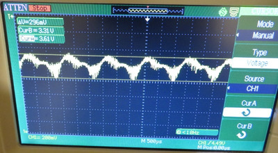
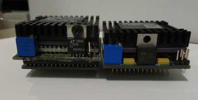
There is a relatively large jump in the voltage required to operate the SXL2 at 75 MHz vs. 80 MHz.

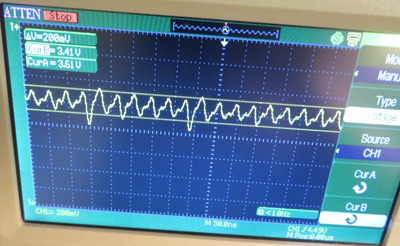
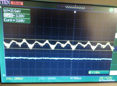
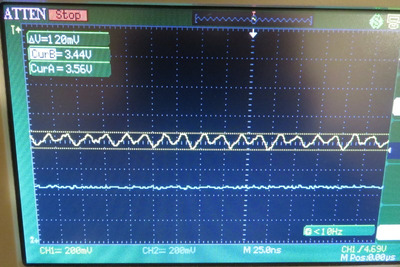
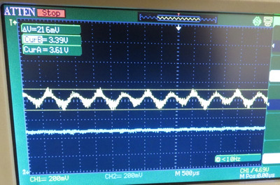
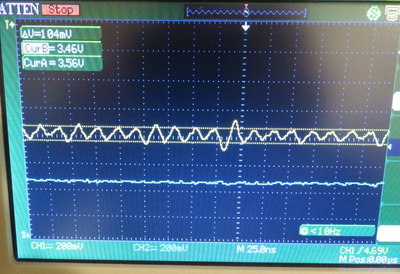
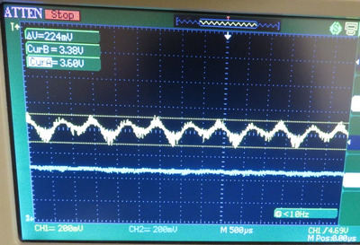
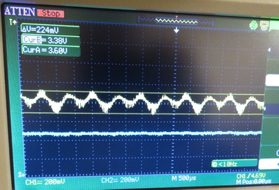
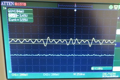
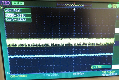
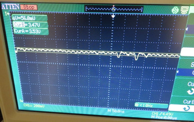
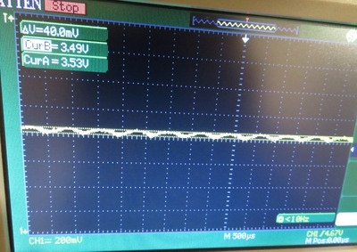
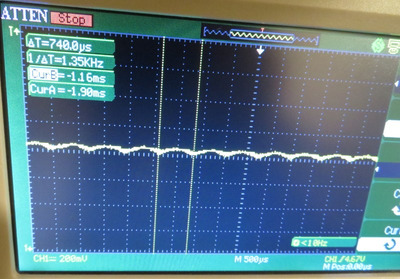
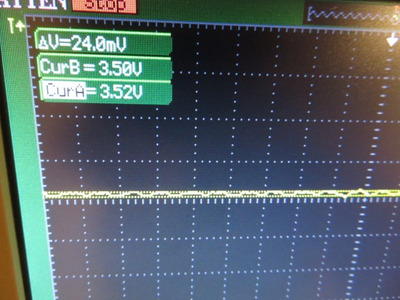
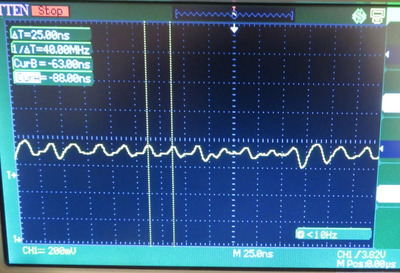
At 75 MHz, I am running the CPU at 3.60 V as based on what my multi-meter says. My scope, on the other hand, calls this 3.50 Vrms. I'm not sure why the reading is so different. Although I don't have a DMM that is true RMS, it should do some averaging to approach RMS. Thus, when I list off voltages, I will be listing both what my scope says and what my DMM says.

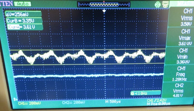
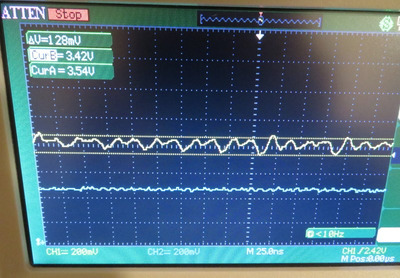
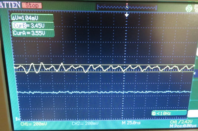
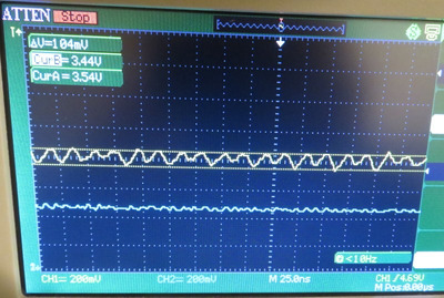
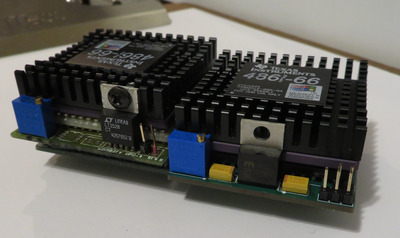
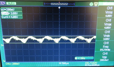
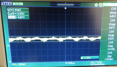
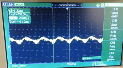
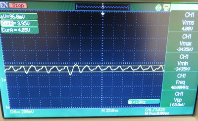
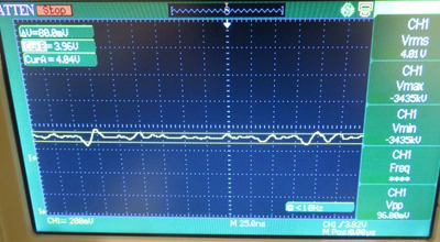
At 80 MHz, to get the CPU stable, there was, again, another variance from CPU to CPU.

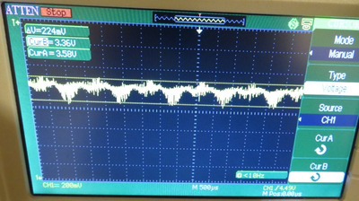
CPU A was stable at 3.80 Vrms on scope, or 3.91 V on DMM
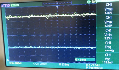
CPU B was stable at 4.00 Vrms on scope, or 4.07 V on DMM
CPU C was stable at 4.05 Vrms on scope, or 4.15 V on DMM

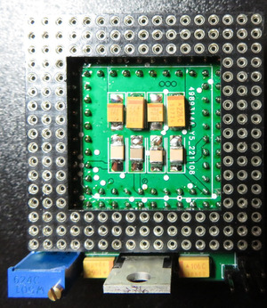
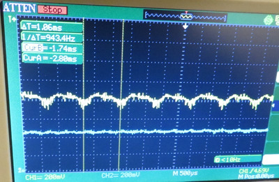
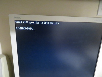
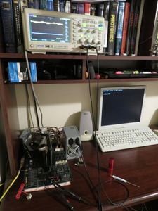
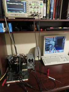
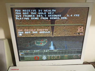
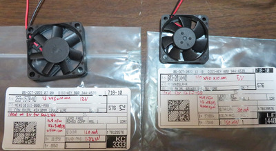
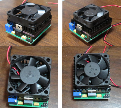
I found that Quake running in loop to be the easiest to perform stability metric. I let it run for 3 hours. However, even though the CPU doesn't get hot, I needed to affix a fan. Without the fan, Quake crashed after 5 minutes. The CPU was only getting up to about 33 C when it would crash. I am using a very low CFM fan, more on that later on. The ambient temperature during test was 16 C, so your results may vary.

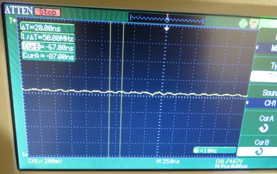
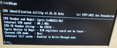
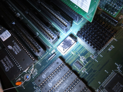
I found that this particular 80 Mhz oscillator to be the best. Meaning that at only 3.60 V, I tried all my oscillators at 80 Mhz and this was the only one that would complete CHKCPU. At higher voltages, they all work though.

Best_80MHz_OSC.JPG
Filename
Best_80MHz_OSC.JPG
File size
491.04 KiB
Views
516 views
File license
CC-BY-4.0
Final_at_80MHz_Full_setup_DOOM-2.JPG
Filename
Final_at_80MHz_Full_setup_DOOM-2.JPG
File size
306.68 KiB
Views
516 views
File license
CC-BY-4.0
Final_at_80MHz_Full_setup_DOOM-1.JPG
Filename
Final_at_80MHz_Full_setup_DOOM-1.JPG
File size
305.47 KiB
Views
516 views
File license
CC-BY-4.0
Final_at_80MHz_DOOM.JPG
Filename
Final_at_80MHz_DOOM.JPG
File size
35.37 KiB
Views
516 views
File license
CC-BY-4.0
Final_at_80MHz_Quake.JPG
Filename
Final_at_80MHz_Quake.JPG
File size
139.51 KiB
Views
516 views
File license
CC-BY-4.0

Plan your life wisely, you'll be dead before you know it.

Reply 556 of 1184, by feipoa

User metadata
Rank l33t++
Rank
l33t++

I also ran Windows 3.11 and opened a bunch of RAM heavy apps.

Final_at_80MHz_Full_setup_Windows3.11.JPG
Filename
Final_at_80MHz_Full_setup_Windows3.11.JPG
File size
661.76 KiB
Views
516 views
File license
CC-BY-4.0
Final_at_80MHz_Windows311.JPG
Filename
Final_at_80MHz_Windows311.JPG
File size
147.97 KiB
Views
516 views
File license
CC-BY-4.0

As for the fan, either a 40 mm or 45 mm fan will fit. These are the two I bought:

Fan_options_45mm_and_40mm_at_5V_label.JPG
Filename
Fan_options_45mm_and_40mm_at_5V_label.JPG
File size
205.18 KiB
Views
516 views
File license
CC-BY-4.0

The 40 mm fan is a 5 V fan and is whisper quiet. It is more than sufficient for 80 Mhz. I also bought a 45 mm fan that runs nominally at 12 V, but also works fine at 5 V and is quiet. Which looks better? I felt that maybe the 45 mm fan was a bit overbearing on the design.

Fan_options_45mm_vs_40mm.JPG
Filename
Fan_options_45mm_vs_40mm.JPG
File size
647.73 KiB
Views
516 views
File license
CC-BY-4.0

Plan your life wisely, you'll be dead before you know it.

Reply 557 of 1184, by feipoa

User metadata
Rank l33t++
Rank
l33t++

At this point, I'm "all done" with displaying the waveforms and results. I will wait for any comments on how to improve the noise on the existing design before providing photographic assembly instructions and the BOM. The reason for wanting to reducing the noise on Vcc is because I've only tested this one one system. Maybe another system won't do as well with the existing noise? Or maybe another user doesn't want to run it in non-clock-doubled mode, where the noise will be higher. Recall the noise is about around 300 mV in 1x mode and 160 mV in 2x mode. Finally, notwithstanding the above, it would feel good for completeness to optimise the device as much as possible.

If you are interested in assembling one of these, but don't want to spend the $81 USD for a batch of these units, I may be willing to send some of my extra PCB's out at cost. For sphere's efforts, I will try to scrounge up some extra pieces to make him a unit. Caps might be a bit different though.

Last edited by feipoa on 2022-12-02, 00:53. Edited 1 time in total.

Plan your life wisely, you'll be dead before you know it.

Reply 558 of 1184, by feipoa

User metadata
Rank l33t++
Rank
l33t++

I knew I was forgetting something. Actually, I'm sure there's quite a bit I forgot to include. The natural next question is, "did you try over 80 MHz"? Yes I did, but the next up DIP-14, 4-pin crystal oscillator I have is 90 MHz. I deliberately selected an ultra-low drop-out regulator for this project for the explicit purpose of taking the CPU up as close to 5 V as I can get. In this case, that translates to 4.66 V. Unfortunately, even at this voltage, I wasn't able to run DOOM or Quake. Maybe a peltier is needed? Maybe some cherry picking of the CPUs? I only have 3 on hand.

I would like are some DIP-14 crystal oscillators in the 81-89 MHz range. Has anybody seen these? I have one that is 87.5 MHz from MF Eelctronics, but the screen stays blank with this installed. Also, those crystals heat up, so it probably has some characteristic that is not appropriate for use in my motherboard.

Plan your life wisely, you'll be dead before you know it.

Reply 559 of 1184, by Sphere478

User metadata
Rank l33t++
Rank
l33t++

Definitely the larger fan

So am I understanding correctly, You were able to get equal overclocking results with our interposer as with a factory unit the only thing deficient that you noticed was power quality but it did not affect results?

I would like to see what the waveform looks like when you power the interposer from a laboratory psu or a large ah lithium battery

Are the regulators between the two units pin compatible? Can you swap them real quick?

Last edited by Sphere478 on 2022-12-01, 13:36. Edited 1 time in total.

Sphere's PCB projects.
-
Sphere’s socket 5/7 cpu collection.
-
SUCCESSFUL K6-2+ to K6-3+ Full Cache Enable Mod
-
Tyan S1564S to S1564D single to dual processor conversion (also s1563 and s1562)