Those look like fun reads, I'll try to get to them.
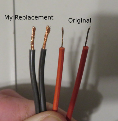
No, I haven't tried with the RAM removed. I can do that before I add caps to the PGA pins.
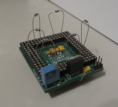
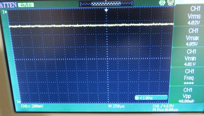
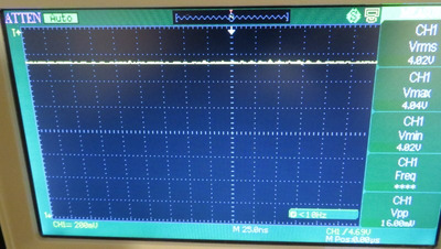
Stalled - if you get an NMI parity error for one. This might happen when the voltage is set too low and you clock double, like from 45 MHz to 90 MHz, then PARITY ERROR. I don't recall the exact error, but it was something like ROM... PARITY... ERROR. If it is important I can try to replicate it. Also, if I install my red prototype unit and try to run it at a frequency it doesn't care for, system won't turn on but the voltage readout on the scope is clean (low noise).
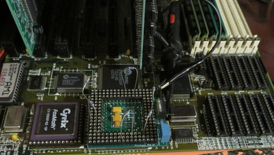
Yes, I am going to remove a cap on my Gainbery unit to measure it. I won't be desoldering any of the four ceramic caps from my exceedingly rare Evergreen SXL2-66 QFP adaptor.
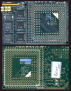
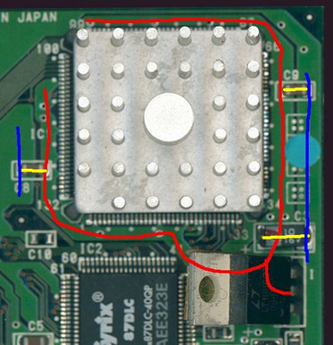
Curious how this transcomputer modules which plug into a 486 and let you run an Am5x86 at 160 MHz, yet don't have any caps. And notice also how the Transcomputer module used a double through-hole approach, like the replica unit under test.
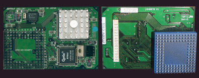
And how this IBM Blue Lightning interposer only has 2 ceramics around the CPU.
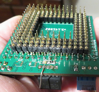
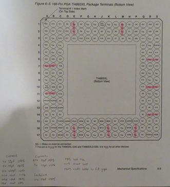
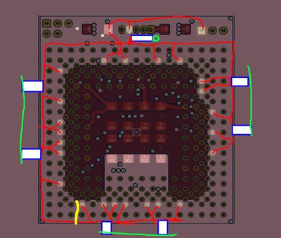
Makes me feel like the effort to solder these 10 caps onto the replica interposer will be fruitless. Anyway, I've mapped out the 10 most probably locations to solder caps to. In my bin, the caps I have which will fit are:
Ceramic
4x 33 pF 0805
8x 47 pF 0603
10x 220 pF 1206
20x 10 nF 1206
100x 10 nF 0603
100x 100 nF 0805
60x 10 uF 0805
9x 10 uF 1206
Tantalum
10x 10 uF 0805
I find the best fit is 0805, provided the existing soldering isn't to thick. Next best is 1206 because I can lay it sideways next to the pins. Worst is 0603, which is the smallest, and the gap between the cap and the through-hole pin might be a bit more difficult to fill with solder.
Plan your life wisely, you'll be dead before you know it.