First post, by Eleanor1967
Hey people,
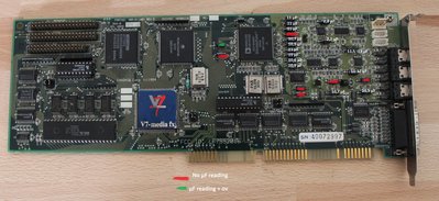
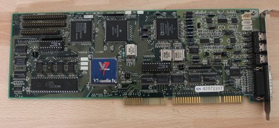
I'm trying to repair a Ensoniq Soundscape S 2000 clone, the Spea Media fx. I just checked the capacitors and found 7 dead ones, should be a good place to start. The thing is that some capacitor have unexpected ratings, for example the one dead capacitor in the row of the 10 caps (I hope you know what I mean, the ones next to the Analog Devices chip) has a rating of just 1µF instead of 10µF like any other in the row. The soldering job looks factory but I just wanted to double check. The problem now is that I couldn't find any picture on the internet of my exact card, all other have a different layout in the top right corner of the card.
So question is does anybody have a card that looks like mine and could check the ratings on the marked caps ?
Best regards,
Eleanor1967