First post, by Adrian_
I recently got involved in a social project which essentially consists in fixing computers from the P4 era, making them capable to competently run Win 7 (2Gb RAM, Dx9 card) then donating them to various establishments (like orphanages) or simply to poor kids who don't own a computer at all.
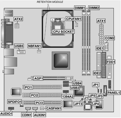
While replacing mountains of bulged capacitors from various motherboards and usually seeing them coming back to life I ran into an Acer T310 computer which wouldn't boot at all, despite my best efforts. The motherboard is an ECS SF2/661FX ver 1.1 and the manual for it appears to be long gone from the ECS website. On both links related to the various implementations of this board the only thing to be found is the manual for the v 2.2 SF2/661FX motherboard. http://www.ecs.com.tw/ECSWebSite/Product/Prod … anID=0#Overview
However the major difference between V 1.1 and V 2.2 appears to be that V2.2 has SATA but it also has only 2 jumpers, one for write protecting the BIOS and one for clearing the CMOS. However the V 1.1 has 4 more jumpers near the CMOS area and without the damn manual I have no clue what these do. They may very well be used for setting the FSB or whatever.
I even found the service manual for the Acer T310 computer but the geniuses who made it presented at the beginning the correct picture for the V 1.1 board they actually used, but in the jumpers section reffered to the 2.2 version of the board. Doh.
So, if anyone has the manual for the V 1.1 of the ECS SF2/661FX or is familiar with the Acer t310 computer, please advice. Your help will be greatly appreciated. 😀