Where did you get it at that price? Do they have one more? 😁
Also, one of the dip switches allows to choose between 0 and 1 wait states, and there is also a jumper for ram compatibility - forgot which one, but it's all in the manual.
I got it from Poland. The board does require some work though, I think it has to do with memory timing. Which version of the manual are you reading? Mine mentions jumpers, but no DIP switch. I'd love to have a look at it and set it to 1 wait state, as when I put 4x256 (for 1Mb) I get "invalid Switch" error JUST as the ram count begins. If I put in 70NS 1Mb SIMMS, it boots OK but later it crashes. I put 60NS RAM in there now and it's quite a bit more stable.
Can you post (or pm me) edge-on photos of the crack? I'd like to see how close the wires are. And I've repaired microSD traces smaller than the bond wires in standard ICs.
Sorry for bumping old thread. Do you manage to repair you MB? I got the same MB, but it has broken BIOS and on vogons none of listed aren't work with my MB. Could you post here a BIOS dump of all you MB 286 with Headland chipset?
Can you post (or pm me) edge-on photos of the crack? I'd like to see how close the wires are. And I've repaired microSD traces smaller than the bond wires in standard ICs.
Sorry for being a few years too late, somehow I managed to miss your post. I actually thought about this and took some macro photos, but no bond wires can be seen.
Sorry for bumping old thread. Do you manage to repair you MB? I got the same MB, but it has broken BIOS and on vogons none of listed aren't work with my MB. Could you post here a BIOS dump of all you MB 286 with Headland chipset?
I now have another two working Fox M boards, but sadly the original one is still broken (it works if I swap the PAL chip from one of the working boards). So if anyone knows someone that can clone such a PAL, please let me know.
Anyway, here's the BIOS:
The attachment Octek Fox M.rar is no longer available
hkzlab has made the DuPAL dumping system: https://github.com/DuPAL-PAL-DUmper
It goes through all pin combinations to derive the full function of a PAL chip.
That would require putting together the PCB, but it's really great that there's a possible solution now 😀
quicknickwrote on 2021-08-07, 20:10:Sorry for being a few years too late, somehow I managed to miss your post. I actually thought about this and took some macro pho […] Show full quote
Can you post (or pm me) edge-on photos of the crack? I'd like to see how close the wires are. And I've repaired microSD traces smaller than the bond wires in standard ICs.
Sorry for being a few years too late, somehow I managed to miss your post. I actually thought about this and took some macro photos, but no bond wires can be seen.
Sorry for bumping old thread. Do you manage to repair you MB? I got the same MB, but it has broken BIOS and on vogons none of listed aren't work with my MB. Could you post here a BIOS dump of all you MB 286 with Headland chipset?
I now have another two working Fox M boards, but sadly the original one is still broken (it works if I swap the PAL chip from one of the working boards). So if anyone knows someone that can clone such a PAL, please let me know.
Anyway, here's the BIOS:
Octek Fox M.rar
Good luck with reviving your board!
Thank you for BIOS dump. I'll try it as I get some free time.
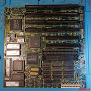
The chip labeled 089-001 seems to be common between our boards, but the similarities end here. The Fox M is also equipped with 090-103 and 090-110, whereas your board has a 090-101 and a mysterious/optional one right next to the battery (board works fine without it, from what I understand following the dosforum.de thread). Nevermind that, I guess I'm too tired. That board also dead as a stone, maybe 3rd PAL is not optional after all...
The chipset pins don't look very bad (un-salvageable) at first glance, but it's hard to tell without higher resolution pictures.
I'll attach the chipset's datasheet here, maybe your board is built according to the reference schematic (Fox M obviously isn't, as it features a third PAL).
Obviously, if you manage to get it going, I'm still very much interested in the content of the 089-001 chip. Although I have amassed a bunch of working Fox M boards, I still want to cross the original one off the "to be repaired" list. 😁
Headland GC101-102.pdf
No luck with the PAL chip so far? I went ahead and recreated PAL equation from datasheet, seems to be working as intended at Proteus simulation.
No luck with the PAL chip so far? I went ahead and recreated PAL equation from datasheet, seems to be working as intended at Proteus simulation.
Few days have passed. And another month on top of them. Only today I was able to find time to set up the board and try your JED file, programmed it into a ATF16V8B but no luck unfortunately. The board still gives the "no RAM" error, so I guess there are some differences between the reference design and my board. Could be some pins shuffled around, or maybe different/more functions are implemented.
Thank you very much for your effort!
Hi.
I have the same board FOX M286 and the same problem - PAL 089-001 is very hot when i power-up the MoBo! And also 3 beeps - NO RAM.
I'll try to find the difference between REF-design and this M286 revision. Will trace all 18 signal wires from this PAL chip. If they are the same as REF - then something wrong with SW or chip programming.
Hi!
If you manage to reverse-engineer the chip, please let me know. I haven't given up yet on repairing the board, but I just lack the skills to do it so I'm patiently waiting 😀
There might be differences between the ref.design and the Octek board regarding these PALs... There's three of them on the Fox and I think only two in the reference design...
In EQUATIONS (programm listing for PAL16L8 U49) is missing generation of output signal ERD .
This output signal is also used in equations of RAS0 and RAS1 and RAS .
All this signal are incorrect due missing ERD signal!!!
That's great, congrats! Does this mean you finally cracked the code inside 089-001 and you have a working board? If so, can you please share the JED file?
Thank you.
Not yet. Just finished schematic reconstruction of Delay line circuit that use this 2 PAL16L8.
Now have to write new equations for PLM!
Will contact you when my board will power up with a single BEEP! 😉
Subequations "NOT(RAS0 + RAM0RAS*ERD)" and "NOT(RAS1 + RAM1RAS*ERD)" was already implemented inside PAL.
Thus they have to be removed from inside equations.
Will get new definition for RAS0 and RAS1 pin definition (Without NOT, because this signals will be inverted by 74S51 outside):
without sum of RAM0RAS * /ERD to RAS0 and without sum of RAM1RAS * /ERD to RAS1
This sum is already implemented outside by 74S51.
Now we have to compile new equations for PAL16L8 using PALASM4.
The resulted JED file must be converted from PAL16L8 to ATF16V8
using PALTOGAL utility, using option "2": PAL16L8 -> GAL16L8
That's great, thank you guys! I'm away at the moment, but can't wait to burn the code into an ATF and revive my board!
@REDLED, I'll have to read into this "Retro Chip Tester Professional", and also I find it interesting that your board lacks the third PAL (the one behind the ISA slots), and one of the other two seems to be a different version to what I've seen so far.