VOGONS


Toshiba T5200 mods and upgrades

Topic actions

Reply 440 of 539, by shimart

User metadata
Rank Newbie
Rank
Newbie
yourepicfailure wrote on 2021-08-26, 05:27:
Getting at all the electrolytics on all the boards are a good idea to get at while you're in there. I see you also removed the l […]
Show full quote

Getting at all the electrolytics on all the boards are a good idea to get at while you're in there.
I see you also removed the left and right inverter boards. I'd swap the electrolytics on those.
Electrolytic, in regards here, is still electrolytic. No matter the type they can still leak, degrade or otherwise fail and cause wierd things to happen. Axials are essentially another making of electrolytic.
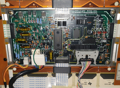
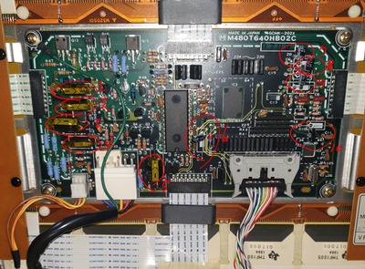
The only electrical properties that matter are the capacitance and voltage rating. You can go as high as you want with the voltage rating, as long as it'll physically fit, but never lower than the original. You can't, however, use a capacitor of different capacitance.

This is the PDP from a T3100SX. The two removable boards in the red boxes are the inverter boards I'm referring to.
pdp.jpg

Thank you for the picture.

The structure of T3200sx seems to be different.
It is estimated that the substrates on the sides are incorporated into the central substrates.

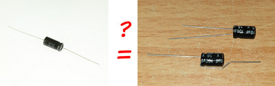
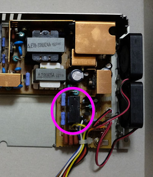
Can I replace it in the same way as the ALUMINUM ELECTROLYTIC AXIAL capacitor picture below?
(Of course, it's a capacitor of the same capacity.)

20210826_193151.jpg
Filename
20210826_193151.jpg
File size
280.52 KiB
Views
1593 views
File license
Public domain

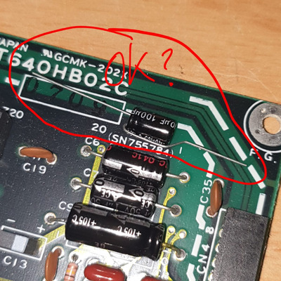
I expect advice from people with electronic knowledge.

Reply 441 of 539, by Vipersan

User metadata
Rank Oldbie
Rank
Oldbie

When it comes to capacitors ...
The same value or slightly larger are generally ok.
The same applies to voltage..
In both cases Capacity and Voltage ...its very unwise to go lower than the rated values of the original.
It goes without saying attention must be given in regards to polarity...when applied to electrolytics of any type.
Same rules apply to Tantalums
rgds
VS

Reply 442 of 539, by BitWrangler

User metadata
Rank l33t++
Rank
l33t++

Voltage on caps, don't go lower than manufacturer puts in, even if it seems okay... for instance, one LCD TV I was into, a 25V cap was blown, but I only had anything close in 16V, but I couldn't see how that part of the circuit was running any higher than 12V... so I put the 16V in... and phut! as soon as I powered it up 🤣 ... I guess mayyyybe they were right on that one.

Unicorn herding operations are proceeding, but all the totes of hens teeth and barrels of rocking horse poop give them plenty of hiding spots.

Reply 443 of 539, by shimart

User metadata
Rank Newbie
Rank
Newbie
Vipersan wrote on 2021-08-26, 13:56:
When it comes to capacitors ... The same value or slightly larger are generally ok. The same applies to voltage.. In both cases […]
Show full quote

When it comes to capacitors ...
The same value or slightly larger are generally ok.
The same applies to voltage..
In both cases Capacity and Voltage ...its very unwise to go lower than the rated values of the original.
It goes without saying attention must be given in regards to polarity...when applied to electrolytics of any type.
Same rules apply to Tantalums
rgds
VS

My question is whether the ALUMINUM ELECTROLYTIC AXIAL capacitor is the version that only changed the pin shape of the normal capacitor.

Is there anyone who can tell me about this?

Attachments

Reply 445 of 539, by snufkin

User metadata
Rank Oldbie
Rank
Oldbie

They're just a different shape (axial/radial). Leg length sometimes matters, but not for this (I think). If you bend the leg around like that then it's a good idea to use a pair of needle-nose pliers to hold the leg where it goes in to the can, so that you don't put an internal stress on the leg. Also watch out to make sure nothing can touch the leg that now runs along the side of the can, or put some plastic sleeving over the top. Make sure to get the +/- legs connected correctly or the capacitor might explode.

Reply 446 of 539, by shimart

User metadata
Rank Newbie
Rank
Newbie
IanB wrote on 2018-01-31, 22:41:
Here are details for the external floppy drive mod. Use this info at your own risk, don't blame me if you damage your T5200! Not […]
Show full quote

Here are details for the external floppy drive mod. Use this info at your own risk, don't blame me if you damage your T5200!
Note that although general file access appears to work on a standard T5200, the OS will think the drive is a 1.2MB 5.25" floppy so booting and formatting won't work.
If you update your BIOS with any of the versions I posted earlier in this thread then these problems are fixed and the OS will recognise the drive as 1.44MB 3.5"

First fit a 34 way IDC header on to one end of a 34 way ribbon cable and then wire up the other end to a 25 way 'D' connector as follows:

wire 2 to pin 14 (Density select)
wire 4 not connected
wire 6 not connected
wire 8 to pin 2 (Index)
wire 10 not connected
wire 12 to pin 10 (Drive select)
wire 14 not connected
wire 16 to pin 11 (Motor on)
wire 18 to pin 16 (Direction)
wire 20 to pin 17 (Step)
wire 22 to pin 12 (Write data)
wire 24 to pin 13 (Write enable)
wire 26 to pin 3 (Track 0)
wire 28 to pin 4 (Write protect)
wire 30 to pin 5 (Read data)
wire 32 to pin 15 (Side select)
wire 34 to pin 6 (Disk changed)

wires 1,3 to pin 20 (Ground)
wires 5,7,9 to pin 21 (Ground)
wires 11,13,15 to pin 22 (Ground)
wires 17,19,21 to pin 23 (Ground)
wires 23,25,27 to pin 24 (Ground)
wires 29,31,33 to pin 25 (Ground)

Connect a 1N5818 schottky diode between pin 1 (ready) and pin 11 (Motor on) with the banded end towards pin 11

Cable + Gotek Floppy emulator:
FloppyCable1.jpg
'D' Type connector pins 1-13
FloppyCable2.jpg
'D' Type connector pins 14-25
FloppyCable3.jpg

Closeup of modified Gotek emulator with flash floppy firmware, Oled display and rotary encoder mods
FloppyCable4.jpg

To use: Plug the cable into the printer port and set the control switch on the left hand side of the keyboard to the "A" or "B" position depending on whether you want the external drive to be "A" or "B" (You can boot from it when set to "A")
Set the switch back to PRT to use the printer port as normal.

I have designed an external floppy drive connector.
I uploaded a circuit diagram and GERBER file.
I hope you watch it for fun.

Cap 2021-08-30 19-55-56-636.png
Filename
Cap 2021-08-30 19-55-56-636.png
File size
115.98 KiB
Views
1533 views
File license
GPL-2.0-or-later
Cap 2021-08-30 19-55-44-158.png
Filename
Cap 2021-08-30 19-55-44-158.png
File size
100.65 KiB
Views
1533 views
File license
GPL-2.0-or-later

Attachments

Reply 448 of 539, by shimart

User metadata
Rank Newbie
Rank
Newbie
snufkin wrote on 2021-08-26, 18:04:

They're just a different shape (axial/radial). Leg length sometimes matters, but not for this (I think). If you bend the leg around like that then it's a good idea to use a pair of needle-nose pliers to hold the leg where it goes in to the can, so that you don't put an internal stress on the leg. Also watch out to make sure nothing can touch the leg that now runs along the side of the can, or put some plastic sleeving over the top. Make sure to get the +/- legs connected correctly or the capacitor might explode.

I changed all the capacitors and it works well!
Plasma screens come out bright and well.
I'm so happy.

20210917_114644.jpg
Filename
20210917_114644.jpg
File size
1.56 MiB
Views
1493 views
File license
Public domain
20210917_115156.jpg
Filename
20210917_115156.jpg
File size
1.58 MiB
Views
1492 views
File license
Public domain

Reply 449 of 539, by 16ShadesOfOrange

User metadata
Rank Newbie
Rank
Newbie

Hey guys, I finally sourced a replacement PSU for my T5200 but get this - it has the exact same issue as my old one 😲.

The manual says the yellow wire should be pumping out +24v... But it's dead on both PSUs.

What are the chances!?! If anyone has any thoughts plz let me know 🤷‍♂️

Attachments

💻 Toshiba T5200 info
💻 Toshiba T3200SX info
💻 Toshiba T3200 info

Reply 450 of 539, by Vipersan

User metadata
Rank Oldbie
Rank
Oldbie

What does the output on the yellow wire (24v) read if it is disconnected from the system ?
Could it be that whatever is being driven by the 24v line has a short or partial short ...thus dumping the 24v when connected ?
Try disconnecting it ..and just this line...by cutting the wire or desoldering....just to see if the 24v is present when not loaded.

After disconnecting the 24v line check the resistance to ground of the 24v line at the system board.
If low ohms then you may well have a fault still ...and both psus then need to be tested to see if any damage has ocurred.
Long odds against both psus having the same fault..
What is likely is that something attached to the psus on the 24v line is either dumping the 24v ...or damaged both power supplies.
rgds
VS

Reply 451 of 539, by 16ShadesOfOrange

User metadata
Rank Newbie
Rank
Newbie

Thanks Vipersan! I actually tested the replacement supply before installing it in the Toshy - I wanted to check if it was better than my busted one.

12V and 5V readings were fine, there's just no 24V. I installed it anyways and the machine runs, but still no 24V hitting the mainboard.

That's why I'm scratching my head! It seems either the manual's wrong or the replacement PSU is bad 🤷‍♂️. Pretty disappointing as it took ages to find one and get it shipped half way across the globe 🌍

💻 Toshiba T5200 info
💻 Toshiba T3200SX info
💻 Toshiba T3200 info

Reply 452 of 539, by TronadaSport

User metadata
Rank Newbie
Rank
Newbie
IanB wrote on 2018-01-16, 04:10:
I have three of these old orange gas plasma 386 machines and have made various mods and upgrades for them over the years and tho […]
Show full quote

I have three of these old orange gas plasma 386 machines and have made various mods and upgrades for them over the years and thought I should document them here in case anyone else is interested in doing the same upgrades.
Here is a brief summary of the mods:

1. Fitted CF cards (two different mounting options)
2. Made up adapter cables to fit ordinary floppy drives internally
3. Fitted Cyrix/TI 386 to 486 upgrade processors including adding hardware support where required.
4. Made up an adapter cable to use an external floppy drive on the printer port.
5. Made up an adapter to use ordinary 72 pin SIMMs for RAM upgrade
6. Fitted 2 extra ISA cards in the space where the Hard Drive was originally fitted giving 4 ISA cards total.
7. Patched the BIOS to support all the above
8. Made a custom build of XTIDE to integrate with the BIOS and support large CF cards on the standard IDE port
9. Used Grub4DOS to create a multiboot system booting an effectively unlimited number of operating systems from the same CF card (currently 20 OS)

When I first got them, the HDs in all three and two of the floppy drives were dead so the first things I did was to fit CF cards and make up adapter leads so that I could use normal floppy drives. The CF cards (master and slave) can be changed by just removing the keyboard instead of having to dismantle the entire machine.

CF1-2.jpg
CF3-4.jpg
I upgraded the CPUs using a Cyrix 486DRx2, a TI 486SLC2 and a TI 486DLC and modified the motherboard to add the A20 gate and Flush signals to the CPUs where required:

CPU.jpg
The T5200 has an option to connect a second floppy drive to the printer port which can be switched as either the A: or B: drive so I made up a cable and used it with a Gotek USB floppy emulator with FlashFloppy firmware.

Gotek1-2.jpg
(continued in next post)

Hello lanb, would it be possible to make a modification in a Toshiba T1850 to replace the original Conner hard drives with CF cards and have these computers updated?
Can someone help me solve this problem?

Reply 453 of 539, by pentiumspeed

User metadata
Rank l33t
Rank
l33t

Check that the 24V rail is not shorted on the computer. Does service manual say anything about 24V rail separate from the rest and is switchable off or on?

Cheers,

Great Northern aka Canada.

Reply 454 of 539, by 16ShadesOfOrange

User metadata
Rank Newbie
Rank
Newbie

Thanks guys, the PSU might be a red herring here, even though the manual seems to indicate that 24V should be pumping out even when the PSU is isolated. I found there's a relay in the PSU that gives out the 24V when engaged (see pic).

So I cracked the relay open and found it wasn't turning on at all while using the Toshy - but here's the thing - I manually triggered the relay and there's no improvement or changes to the screen image.

I'm thinking that something in the converter board/screen is not firing properly - I'm guessing when it does, it signals the PSU to fire up the 24V and trigger the relay.

It's all guesswork but I'm gonna try re-capping the screen and converter board 🤷‍♂️

Attachments

Reply 455 of 539, by nullman

User metadata
Rank Newbie
Rank
Newbie

I'm trying to get my, recently purchased T5200, working with @IanB's Award BIOS. Specifically: T5200 BIOS V5.30 (Award) patch 1.2 with LOMEM XTIDE 640K.BIN

I've programmed it onto an AM27C1024 EPROM and it works great as long as I use 8GB or smaller drives/CF cards. However, I can use CF cards (and presumably drives) larger than 8GB using my XTIDE Deluxe 8-bit ISA card, and I'd like to get this same functionality.

I'm thinking/hoping I just need to create my own XTIDE BIN with LBA support and replace the XTIDE section in the BIOS with my version (at C800-D7FF). I've tried doing this, but I get a BIOS checksum error when I turn on the machine. I've tried to determine and set the checksum, but I haven't been able to figure it out.

Can someone who knows how this works let me know if I'm doing the correct thing by copying my custom XTIDE BIN data to that BIOS memory location and let me know how to correctly determine and set the checksum?

Or if someone has already made a T5200 BIOS version that supports LBA and would like to post the file, that would be even better. (If one is already in this thread do let me know.)

Thanks, Kyle

Reply 456 of 539, by Jesuswald

User metadata
Rank Newbie
Rank
Newbie
ConventionalMemories wrote on 2020-12-22, 22:49:
Hmm seems like there isn't any BIOS patch available already for the t3100e. so this seems like a good time to introduce my proj […]
Show full quote

Hmm seems like there isn't any BIOS patch available already for the t3100e.
so this seems like a good time to introduce my project to this forum.
https://www.benl.ebay.be/itm/264877993192

This is an expansion card that goes into the special toshiba expansion slot.
It provides an XT-IDE BIOS in ROM as well as an CF card slot that's easily accessible from the back of the machine.
It is compatible with many Toshiba portables from the T1100+ all the way up to the T5200

One of the more interesting features that i think many people here will find useful, is that it can also easily be configured to control the internal IDE controller on machines that have one. (T3100e, T3200sx(c), T5100, T5200(c))
This allows you to have both an easily accessible CF card slot as well as the ability to change out the internal drive without running into the restrictions of the Toshiba BIOS.

I hope some of you will find this helpful

Hi ConventionalMemories.
This is a really, really neat project! I currently have both 16 and 8-bit ISA slots filled in my T3200SX and so do not have space for an XT-IDE. Using the expansion slot is a great option. I didn't think anyone would actually manage to figure it out or find the connectors, yet you clearly have.
The eBay link appears to be broken at present. Is there any chance you could let me know how to buy one?

If I recall it was also possible to expand RAM via one of the expansion slots on the T3200SX as well. If you ever have go at a RAM expansion board, sign me up for one of those too. 😀
Many thanks.

Reply 458 of 539, by Jesuswald

User metadata
Rank Newbie
Rank
Newbie
my03 wrote on 2022-02-15, 11:21:

Jesuswalk, idk if you can find more information here: https://conventionalmemories.com/wiki_cm/CF_a … shiba_portables

Thank you!
While the eBay links on that page are also broken, there is a contact form. I'll try that. 👍

Reply 459 of 539, by redjr

User metadata
Rank Newbie
Rank
Newbie

Hello,

Excellent thread and lots of mods for this computer. New member here. I recently brought out an old T5200/100 luggable I used decades ago as a consultant. Haven't used it since 1993! I'm not interested in the many mods here at the moment, but maybe down the road someytime. What I do need is a 3.5" MS-DOS bootable disk for the stock machine. I'm just trying to ascertain whether or not it will boot. I only have a few disks for this machine and none of them are bootable. And I have no external 3.5" drive lying around 😀

I would appreciate it if anyone would be willing to send me a bootable diskette so I can get this thing up and running and possibly for sale. I can get to setup screen, so it will power on successfully.

Another issue I have, is I can't seem to get the screen to come off the top assembly. There is a small screw just behind the screen jack that simply will not come out. I can loosen it, but the screen will not disengage from the mechanism. I don't want to break anything, but from a Youtube video I watched it is suppose to be 'easily' removeable, as well as the top assembly. Any ideas?

I'm glad I found this site and thread, and look forward to following some of mods being discussed here.

Please PM me if you can help with the above request.