VOGONS


First post, by Dracolich

User metadata
Rank Member
Rank
Member

I can't seem to find anything on the 'net about this. Plenty of resources about no beeps on a computer that doesn't work, but that's not my question. My computer works fine, except the internal speaker does not beep during POST and in software that plays through the speaker.
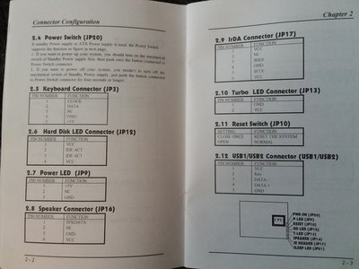
I tried reversing the wire on the header, checked the manual to make sure it's on the right pins and the header pinout is not weird, borrowed a known working speaker from another machine, browsed the BIOS settings numerous times looking for anything about a speaker or beeping.
My mobo is a QDI Titanium IB with BIOS 1.3S, using an ATX PSU if that makes a difference. The only jumper on this board is the one to clear CMOS. I haven't noticed until recently that it has been a long time since I heard a beep from the internal speaker. I would like it to work in case I need to hear POST beep codes.

Reply 1 of 12, by .legaCy

User metadata
Rank Oldbie
Rank
Oldbie

which kind of speaker you are using on the header?
My 486 had problems making a real pc speaker , i used those tiny piezo beeper and it worked, but i never seen anything like it
The only thing that it could be is the pc speaker header connecting to pc speaker input on the sound card.

Reply 3 of 12, by .legaCy

User metadata
Rank Oldbie
Rank
Oldbie
Dracolich wrote:

Thanks for the quick reply. It's not connected to my SB16. It is the older style speaker, like the one on this page:
http://www.suntekpc.com/htm-2/speaker-pc-inte … h-8-ohm-xxx.htm

Do you have one piezo beeper (those new ones) to test with?

Reply 6 of 12, by Dracolich

User metadata
Rank Member
Rank
Member

K, so while I had the case open I took the requested photo, as well as a photo of the manual page that shows the header pinouts. I also got out my multimeter and checked the voltage going to each of the two different speakers. I measured ~3.4V to the piezo and 4.3V to the big speaker. On my main pc, the piezo reads a solid 5.0V. Seems like the QDI is not getting enough voltage to the header. The buttons and LED headers are working properly. All of the caps look good and the battery is only 1-2 years old.

20180615_164554.jpg
Filename
20180615_164554.jpg
File size
1.86 MiB
Views
1181 views
File license
Fair use/fair dealing exception
20180615_164203.jpg
Filename
20180615_164203.jpg
File size
1.46 MiB
Views
1181 views
File license
Fair use/fair dealing exception

Reply 7 of 12, by Dracolich

User metadata
Rank Member
Rank
Member

I should add that the USB and PS/2 headers are on the opposite side of the board, next to the keyboard connector. I do have USB ports and a PS/2 port connected on these headers and they work. I have not tried with them disconnected because it connects to a USB kvm to share the monitor. Also, it's a bloody PITA to reconnect them without pulling out all of the other cables. Lol

Reply 8 of 12, by quicknick

User metadata
Rank Oldbie
Rank
Oldbie

There is a transistor, right behind the speaker header on your photo. Check to see if it's got any connection to the speaker header, if it does then it is the "amplifier" for the speaker signal... Desolder it and check it with your multimeter. Replace if faulty 😀

Reply 9 of 12, by Dracolich

User metadata
Rank Member
Rank
Member

Thanks, quicknick. Looking at that, I found it to be pressed flat against the row of resistors behind it. The legs of the transistor are labeled, from left to right: C, B, E. After standing it up, on the back of the transistor is three rows of numbers: N730, 2N, and 3G04. I don't see any paths from the transistor to the header, unless they're on the back. I'm not about to disassemble the pc to look. It's hard enough to get a close look at the front 🤣

20180615_191625.jpg
Filename
20180615_191625.jpg
File size
1.53 MiB
Views
1149 views
File license
Fair use/fair dealing exception

I'm afraid I don't know enough about electronics and I don't have enough soldering skill to test and replace these small components. And I don't want to risk killing the board while everything else works - it won't be worth it just for the speaker 🤣

Reply 10 of 12, by Dracolich

User metadata
Rank Member
Rank
Member

Sorry for reviving an old thread, but after solving a PnP detection problem by reflashing the BIOS I decided to take another shot at this speaker in case it was somehow related. I tried with the speaker on pins 1-4 and 1-3 but still no luck. Between 6/15/2018 and yesterday I had been using a jumper from the mobo header to a PC_SPK header on my SB16. With volumes set to max in MIXERSET there was still no mobo beeps. I also used Wolfenstein 3D set to pc speaker for testing and had no menu or game sounds.

I ordered and received an active piezo buzzer designed for Arduino/Raspberry Pi https://www.amazon.com/dp/B014KQLE8Q/ref=cfb_at_prodpg This buzzer is designed to operate at a voltage range 3.3 to 5.0, so even if my header is not outputting a full 5.0 this buzzer should respond. It also has diodes D1 and D2+ that light. I hooked it up with SIG to SPKDATA and VCC to VCC and got lights but no sound. So I added the connection GND to GND and now got sound but it was a constant buzz from the moment power comes on.

With the buzzer connected, both with and without GND connected, I also noticed that with the pc powered off diode D1 still blinked every few seconds. It only lit solid and D2+ only lit when power is turned on. I suspect this is due to using ATX power. All of the power saving options are disabled in BIOS.

Reply 11 of 12, by Jo22

User metadata
Rank l33t++
Rank
l33t++

Hi, I believe that active piezo is an alarm siren.. It may work for testing, but it won't produce any music/sound in games (it's no speaker+amplifier).

"Time, it seems, doesn't flow. For some it's fast, for some it's slow.
In what to one race is no time at all, another race can rise and fall..." - The Minstrel

//My video channel//

Reply 12 of 12, by Dracolich

User metadata
Rank Member
Rank
Member

Hi, Jo22, thanks for the reply. Yes, testing is the main purpose of the new piezo...to get a response. The 4-pin header has three labeled pins, and I got no sound until GND was connected. Two known good 2-wire speakers do not work on any combination of two pins.