Roman555 wrote:It's OK.
Could you clarify why so much soldering was done around MOSFETs ? Were they all replaced by working ones?
I'll try to f […]
Show full quote
It's OK.
Could you clarify why so much soldering was done around MOSFETs ? Were they all replaced by working ones?
I'll try to figure out what's wrong but it involves a lot of measures. Something like this. And result is not guaranteed.
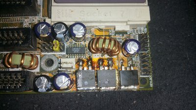
In the red circle there's something like filth. Am I wrong?
Arrows show where probes are applied to measure voltage when the mainboard is turned on. So be very careful. A black probe is always on the ground rail.

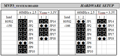
Soldering was done because this board had missing MOSFETs and voltage regulator (although it did POST with new MOSFETs, they were later killed by a K6-2, legit) and I replaced them again now with a new set from a known working Socket 462 KT133 board. While the voltage regulator holds up, I have had the MOSFETs blow with two K6-2s set accordingly. Anything else (like K5 PR100, non-MMX pentium chips and MMX as well) would work fine (with the exception of the MMX which I suspect it's dead as it never POST'd)
The red circle is actually a Zener diode in SOT-323 package which I replaced. Doesn't look pretty but it makes good connection.
Okay:
Diode under fan header: 0.04 Ohms on the left, infinite on the other
Linfinity chip : infinite reading on both pins
Choke between ISA slots: infinite both ways
Voltage regulator: tab gives infinite, right tab gives 4.6 Ohms, left gives infinite
MOSFET in middle: tab gives infinite, right tab gives infinite, left gives 0 Ohms reading
MOSFET in the left: tab gives infinite, right tab gives infinite and left gives infinite as well.
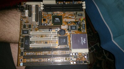
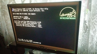
Attached below is a picture I took when I first got it to work.
"Enter at your own peril, past the bolted door..."
Main PC: i5 3470, GB B75M-D3H, 16GB RAM, 2x1TB
98SE : P3 650, Soyo SY-6BA+IV, 384MB RAM, 80GB