VOGONS


First post, by Thermalwrong

User metadata
Rank Oldbie
Rank
Oldbie

I've been after an LS-120 superdrive for a while, because my old retro PC (circa 2002) had one and I sold it off again after that PC broke - and because I really enjoy how quickly they read floppy disks.

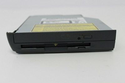
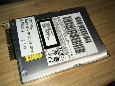
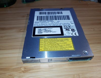
These things are ELUSIVE now, especially in a functional state. I managed to get hold of a broken 3.5" LS-120 drive and had no luck getting that going but kept an eye out. Eventually I spotted what I thought was one Panasonic CF-VFS712 superdrive module for a toughbook, and that turned out to be five superdrive modules - but alas I have no toughbook that would fit this, so I tried dismantling them.

These modules are pretty good if I can get them working because they contain an LKM-FC33-5 drive, which is one of the last superdrives ever made (because they were pretty useless when they were made in mid 2001). It has a laptop optical style 50 pin connector, so I thought it would just work if I plugged it into that 😀

IMG_20180711_215454.jpg
Filename
IMG_20180711_215454.jpg
File size
907.16 KiB
Views
2823 views
File comment
The LKM-FC33-5 SuperDrive
File license
Fair use/fair dealing exception

I tried one of the drives in a laptop optical drive USB caddy, which resulted in the USB port shorting instantly so went back to the drawing board - and spotted this post here:
https://groups.google.com/forum/#!topic/comp. … are/pPe0mb_Ao7c

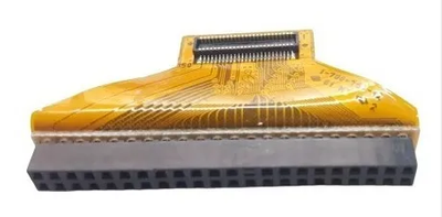
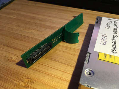
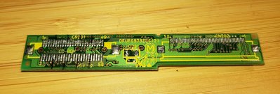
The pinout of the drive is completely different from a regular laptop optical drive, but the caddy contained an interposer board to connect the CD-ROM / LS-120 to the weird toughbook multibay module pinout (which has 160 pins). Conveniently, the CD-ROM traces link to the LS-120 traces

IMG_20180711_215347 (Large).jpg
Filename
IMG_20180711_215347 (Large).jpg
File size
325.67 KiB
Views
2823 views
File comment
The interposer board, which has the connector soldered on to the LS-120 side. The 50-pin flat connector goes to the modular connector
File license
Fair use/fair dealing exception

Initially, I thought I could solder wires onto the CD-ROM connector part, or a regular optical drive connector, but there's no such thing (or need for) a 50 pin ide connector gender changer 😁
Just fitting a connector on there results in the connector being upside-down, with pins 1 to 49 going where pins 2 to 50 go.
Soldering that was Much Too Hard and now I have a practically ruined USB > IDE laptop drive board with a few of the pads burned off...

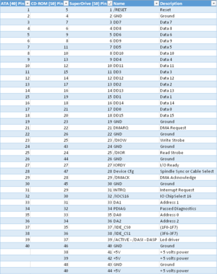
So instead, I checked out what each pin corresponds to on either one, using the table here:
http://old.pinouts.ru/HD/cdrom_40to50_pinout.shtml

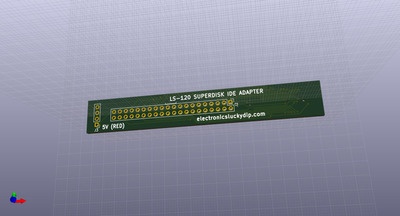
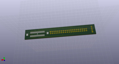
And here's the result, now I feel stupid, since it's just a regular IDE connector but tiny. Of course there is no such connector / adapter that's available to just connect it up, so now I want to try out soldering up some wires so I can actually use the drives:

LKM-FC33 pinout.png
Filename
LKM-FC33 pinout.png
File size
44.48 KiB
Views
2823 views
File license
Fair use/fair dealing exception

Reply 1 of 25, by feipoa

User metadata
Rank l33t++
Rank
l33t++

Are you wiahing to use these in a desktop PC? If so, why not just buy a standard LS-120 drive? Cost?

Plan your life wisely, you'll be dead before you know it.

Reply 2 of 25, by Thermalwrong

User metadata
Rank Oldbie
Rank
Oldbie

I just want to make use of them and I enjoy figuring this stuff out 😀

Also from what I've read, the later model drives (1999 to 2001) work a lot better than the early model ones, which read far slower. I don't think the newer drives are so easy to get, though I could get a newer model 3.5" drive from the states for about double what I paid for these 5 drives (yes it is a little bit about cost).

Reply 3 of 25, by CaelThunderwing

User metadata
Rank Newbie
Rank
Newbie

the bonus the later models had than earlier ones (before you get into the LS240's) is a more stable head and faster reads. i got a USB Version (ones ment for a Mac) and it does read slower than one should expect, (faster than a Parallel Port edition, but slower than one connected over IDE (which you can negate by passing the IDE2USB converter in the casing and connect the drive itself over IDE)

Reply 4 of 25, by feipoa

User metadata
Rank l33t++
Rank
l33t++

Interesting. I had looked into getting one of these a few years back and decided the cost wasn't worth it. I have a bin of about 3 dozen 3.5" floppy drives, so if one dies, I'm set for life. The idea of faster floppy access is very appealing though, as I do not use floppy emulators anywhere.

Plan your life wisely, you'll be dead before you know it.

Reply 5 of 25, by EleDip

User metadata
Rank Newbie
Rank
Newbie

Hi Thermalwrong, hope you don't mind me adding to this thread years later. I've just pulled some LKM-FC33-5 out of some broken Panasonic PV-SD4090 digital cameras, and run into the same issues described above. I tried plugging the drive into a regular 50 Pin JAE to Standard 40 pin IDE Adapter and soon found that the power and gnd lines were shorted, so It's awesome to have found the post above about the pinout. I'm considering designing a PCB to act as an adapter between the LKM-FC33-5 Superdisk drive and 40-pin IDE, but I am and wondering if you ever got the drives working or an adapter made? cheers!

Reply 6 of 25, by EleDip

User metadata
Rank Newbie
Rank
Newbie

Someone messaged me asking if I got my Superdisk drives working with a PC, but apparently I'm not a senior enough member on Vogons to be able to send private messages to reply to the PM I received...

Following my last post I did develop an "interposer board" that converts the slimline IDE connector on the back of the LKM-FC33-5 drives to a regular 40-pin IDE & power connector (using Thermalwrong's pinout above as a guide), and the drives do then work with my P4 motherboard. Woot! The PCBs I've designed also surround the drives to make them into the correct form-factor to fit in a regular 3.5" floppy drive bay, so they can be installed as an internal drive.

Anyway, for anyone interested in these LS120 drives I've uploded a video about it here: https://odysee.com/@electroluckydip:c/superdi … mod_prototype:d

Reply 7 of 25, by 001

User metadata
Rank Newbie
Rank
Newbie

Hi! Yeah, I sent you a PM. I actually found an adapter that can be used to convert jae ide connectors to normal (notebook) ide. The one I have is a "Sony Vaio PCG-R505B/P Hard Disk Cable". Looks like they were common internal adapters in Sony notebooks.

Still, you should upload your kikad files somewhere. I'm not sure if those Sony adapters are easy to find in the wild. Plus I havent tested mine yet, as I couldnt find a slim LS drive for a reasonable price.

Attachments

  • jae-ide50.png
    Filename
    jae-ide50.png
    File size
    87.23 KiB
    Views
    2500 views
    File license
    Public domain

Reply 8 of 25, by Thermalwrong

User metadata
Rank Oldbie
Rank
Oldbie
EleDip wrote on 2021-01-11, 08:36:

Someone messaged me asking if I got my Superdisk drives working with a PC, but apparently I'm not a senior enough member on Vogons to be able to send private messages to reply to the PM I received...

Following my last post I did develop an "interposer board" that converts the slimline IDE connector on the back of the LKM-FC33-5 drives to a regular 40-pin IDE & power connector (using Thermalwrong's pinout above as a guide), and the drives do then work with my P4 motherboard. Woot! The PCBs I've designed also surround the drives to make them into the correct form-factor to fit in a regular 3.5" floppy drive bay, so they can be installed as an internal drive.

Anyway, for anyone interested in these LS120 drives I've uploded a video about it here: https://odysee.com/@electroluckydip:c/superdi … mod_prototype:d

That's brilliant! 😁 I was just thinking about this the other day as a thing I really should get around to. I had a go at it in Eagle a long time ago but wasn't successful since I didn't have much of an idea what I was doing at the time with it. I think I got stuck at trying to make the JAE 50 pin connector in eagle.

I really like your method to make a case for it too, very creative and it looks like it should all fit together really well.
Does it just use glue to connect the separate PCBs?
Having the floppy drive upside down must feel a bit strange to use, but it looks really nice in the case.

Regarding the soldering the JAE connector using solder paste, did you use a stencil to put the paste on or just put it on there? I had the same experience with paste and that pin pitch 😀 I think that pin pitch and solder paste should be okay if a stencil is used and you've got experience with using solder paste, which I haven't got much of.

Reply 9 of 25, by EleDip

User metadata
Rank Newbie
Rank
Newbie

Hey, good to get your replies.

001 wrote on 2021-01-11, 19:52:

Hi! Yeah, I sent you a PM. I actually found an adapter that can be used to convert jae ide connectors to normal (notebook) ide. The one I have is a "Sony Vaio PCG-R505B/P Hard Disk Cable". Looks like they were common internal adapters in Sony notebooks.

Very interesting to see that Sony Vaio cable - looks like the 2.54mm pitch end is 2x24 pins, so not immediately socketable with a standard motherboard IDE which is 2x20, and no obvious power connector.. but you should be able to make it work!

001 wrote on 2021-01-11, 19:52:

Still, you should upload your kikad files somewhere. I'm not sure if those Sony adapters are easy to find in the wild. Plus I havent tested mine yet, as I couldnt find a slim LS drive for a reasonable price.

Thanks for the suggestion! I have uploaded the design files and also made the spare PCB's I had manufactured available, here. There is also a new video discussing its construction.

Thermalwrong wrote on 2021-01-11, 21:17:

Does it just use glue to connect the separate PCBs?

It's held together by the 4 mounting screws after sliding it into a PC's 3.5" floppy drive bay.

Thermalwrong wrote on 2021-01-11, 21:17:

Having the floppy drive upside down must feel a bit strange to use, but it looks really nice in the case.

I'm not sure why the writing on the drive door is upside-down on the drives I got (I guess they were made specifically for the digital cameras I got them from, so not expected to need the same orientation as an internal drive) but the finished adapter + drive is the same way up as a standard drive, at least floppy disks are the right way up when inserted 😀

Thermalwrong wrote on 2021-01-11, 21:17:

Regarding the soldering the JAE connector using solder paste, did you use a stencil to put the paste on or just put it on there?

I was too cheap to order the stencil which added quite a lot to the cost, so I was manually applying the paste, which caused too many solder-bridges to form - especially underneath the connector where they were very hard to rectify. The pads for this connector are too close together to have solder mask between them (the PCB house removed it), almost inviting the solder-bridges to party! When soldering the latest boards without a stencil I've found regular drag soldering is the best option, though I would have messed up the job if I had not practiced extensively on some QFP chips before doing it, and of course I needed to use a microscope.

Not sure what I will do with the drive yet, now that I have it installed... I've read that the LS120 can be great for recovering data from hard to read floppies, so I look forward to experimenting next time I find an unreadable floppy and comparing the LS120 with other floppy recovery options like the Greaseweazle and Fluxengine. Aside from that I'm looking for ideas of what use the LS120 drive could be, if you have any ideas? Using a 120MB SuperDisk as a boot disk is another possible project, but I'm yet to think of a practical reason for it. 😀

yf8mXWGm.jpg

Last edited by EleDip on 2021-01-17, 23:10. Edited 1 time in total.

Reply 10 of 25, by Caluser2000

User metadata
Rank l33t
Rank
l33t

Some industrial systems use LS120 drives to boot. I have a parallel port LS120 drive on my Zenith Z286LP Plus. It's brilliant for copying 3.5" floppies an transferring files to and from the 286.

There's a glitch in the matrix.
A founding member of the 286 appreciation society.
Apparently 32-bit is dead and nobody likes P4s.
Of course, as always, I'm open to correction...😉

Reply 12 of 25, by EleDip

User metadata
Rank Newbie
Rank
Newbie
Rapanui wrote on 2021-02-13, 03:37:

EleDip, would it be possible to have a version of just the pcb to fit in the back of a slim bay, instead of full sized 3.5 bay?

Hi. What kind of slim bay do you mean exactly? If you have a need for a different design you are certainly welcome to take the KiCad files and modify the PCB design for your needs.

Reply 13 of 25, by Rapanui

User metadata
Rank Newbie
Rank
Newbie

Oh, I meant one that fits in the back of the slim drive. As close as the same height and width as possible. I'm want to make a sort of combo drive. I.E. a slim dvd burner from a laptop with a slim ls120 under it. So I cant use a big pcb because it would bump into de dvd drive.

Same idea as the combo drives that came with GateWay laptops, but for a desktop pc.

Attachments

  • s-l1600.jpg
    Filename
    s-l1600.jpg
    File size
    86.96 KiB
    Views
    2262 views
    File license
    Fair use/fair dealing exception

Reply 14 of 25, by EleDip

User metadata
Rank Newbie
Rank
Newbie
Rapanui wrote on 2021-02-13, 17:25:

Oh, I meant one that fits in the back of the slim drive. As close as the same height and width as possible. I'm want to make a sort of combo drive. I.E. a slim dvd burner from a laptop with a slim ls120 under it. So I cant use a big pcb because it would bump into de dvd drive.

Same idea as the combo drives that came with GateWay laptops, but for a desktop pc.

Interesting idea, here's my thoughts: I think it would be pretty simple to size down the LS-120 "interposer board" PCB to be the same size as the rear of the slim drive, and I can upload that somewhere if it would be of use, but I think you would need to have some plan for how it was to clip/screw/glue/attach into the back of the combo drive "enclosure" (which I guess maybe you envision to be 3D printed?), and that may affect the shape of the PCB.

Also something else that came to mind is that if the optical drive was slimline IDE rather than slimline SATA (which it probably should in many cases as the LS-120 is also IDE) then it would follow that the "interposer board" for the optical drive was also part of the overall design, or at least an option so either SATA or IDE optical drives could be.

Reply 15 of 25, by 001

User metadata
Rank Newbie
Rank
Newbie

Yes! A pcb the same size of the drive could be useful in one of my projects. I need a slim drive including front and back, so I cant use the current pcb. In my case, is for a floppy/usb combo in regular 3 1/2 size.
Also, EleDip, I cant download you gerbers file LS120_GERBERSv2.zip. It spits out 403 error "Forbidden You don't have permission to access this resource." I have v1 (its on archive org). What changes did you make? Are you making a v3?

Rapanui, I read in another thread that you are looking for a bezel for slim drives. Me too. There is a guy in eBay selling them but they are 20 bucks each (+50 for shipping to my country). Insane prices. I'm thinking in cutting the front of the caddy that the drive and adapting that into a bezel.

Reply 16 of 25, by weedeewee

User metadata
Rank l33t
Rank
l33t
EleDip wrote on 2021-01-17, 08:02:
001 wrote on 2021-01-11, 19:52:

Hi! Yeah, I sent you a PM. I actually found an adapter that can be used to convert jae ide connectors to normal (notebook) ide. The one I have is a "Sony Vaio PCG-R505B/P Hard Disk Cable". Looks like they were common internal adapters in Sony notebooks.

Very interesting to see that Sony Vaio cable - looks like the 2.54mm pitch end is 2x24 pins, so not immediately socketable with a standard motherboard IDE which is 2x20, and no obvious power connector.. but you should be able to make it work!

it's probably a 44pin laptop IDE connector with a 2mm pitch , the extra 4 pins are for gnd and +5v power.

Right to repair is fundamental. You own it, you're allowed to fix it.
How To Ask Questions The Smart Way
Do not ask Why !
https://www.vogonswiki.com/index.php/Serial_port

Reply 17 of 25, by EleDip

User metadata
Rank Newbie
Rank
Newbie
001 wrote on 2021-02-19, 19:54:

Yes! A pcb the same size of the drive could be useful in one of my projects. I need a slim drive including front and back, so I cant use the current pcb. In my case, is for a floppy/usb combo in regular 3 1/2 size.

Alright, reading your reply above it sounds like you just want the PCB to be the same size as the drive. I've made a "MINI" version by reducing the PCB down as close as I could to the LS-120 slim. Still not sure how you will hold it in place... It's close to the same size as the slimline drive but about 1mm extra on top and bottom to make room for the circuit. Untested obviously. Should work but no guarantees 😀

IMAGE_F.jpg
Filename
IMAGE_F.jpg
File size
196.21 KiB
Views
2121 views
File license
Public domain
IMAGE_B.jpg
Filename
IMAGE_B.jpg
File size
180.77 KiB
Views
2121 views
File license
Public domain
001 wrote on 2021-02-19, 19:54:

Also, EleDip, I cant download you gerbers file LS120_GERBERSv2.zip. It spits out 403 error "Forbidden You don't have permission to access this resource." I have v1 (its on archive org).

Ah thanks, should be able to download V2 now (https://electronicsluckydip.com/store/LS120_Adapter_PCB.html).

001 wrote on 2021-02-19, 19:54:

What changes did you make? Are you making a v3?

With V1 the 1.2mm thickness (Black PCB) wasn't working so well so I went back to the 1.6mm thickness that I had used with the prototype (White PCB). This meant adjusting the slots and tabs etc back to 1.6mm, also the little button was too wiggly and fail in V1 and I'm expecting will be fixed with V2. V2 boards are on their way and I will update after I have a chance to build one. Don't use V1 without adjustments, and V2 is currently untested until I recieve them.

Attachments

Reply 18 of 25, by EleDip

User metadata
Rank Newbie
Rank
Newbie

Well the V2 PCBs arrived and unfortunately needed another tweak as the tabs/slots weren't lining up as well as I'd like. New boards ordered and the files on the website have now been updated to V3. So, about another week until they arrive and then I should be able to mail out the few that have been ordered.

Reply 19 of 25, by Thermalwrong

User metadata
Rank Oldbie
Rank
Oldbie

The PCB for the LS120 Mini adapter arrived and I put it together this evening. Just using the original JAE connector from the drive's original adapter board, since I couldn't get the solder to melt via hot air gun with one salvaged from a Sony Vaio laptop. That would have been good because that one sticks out further, giving more room to attach the PCB and avoid shorting stuff, but oh well.

Because it fits so close, I had to solder on the pins so that they were just fitting in the ends of the holes without sticking out. It looks nice after cleaning the flux off, I'm just using some insulating tape to stop things shorting out.

Superdisk-adapted-3.jpg
Filename
Superdisk-adapted-3.jpg
File size
1.24 MiB
Views
1918 views
File comment
The adapter installed
File license
CC-BY-4.0
Superdisk-adapted-2.jpg
Filename
Superdisk-adapted-2.jpg
File size
596.26 KiB
Views
1918 views
File comment
no shorting
File license
CC-BY-4.0
Superdisk-adapted-1.jpg
Filename
Superdisk-adapted-1.jpg
File size
1.24 MiB
Views
1918 views
File comment
Up and running on my bench testing 486
File license
CC-BY-4.0

Thank you so much for taking the time to make these PCB designs and sharing them, it's really great that now everyone can use these drives instead of just letting out the magic smoke each time 😁