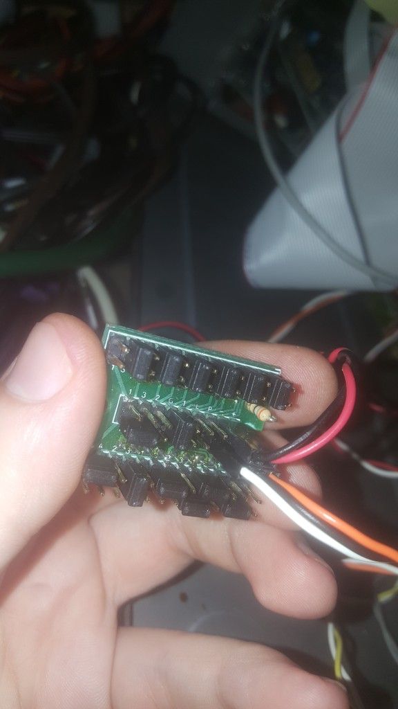
Vaudane wrote:I could be wrong here, but it looks like the LCD is missing a controller on that little board, so there is no way to hook that directly up to the motherboard. My guess would be that was a daughter board for the controller-board that the lead attached to.
Thanks for your help! It appears in this case the display is "dumb", it doesn't actually know what its displaying, just that it is jumpered a certain way, even the signal from the turbo button is interpreted (I believe) as just a jumper changing, so the display changes to the other set of numerals. I believe that this negates the need for a controller, but what the heck do I know?
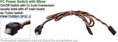
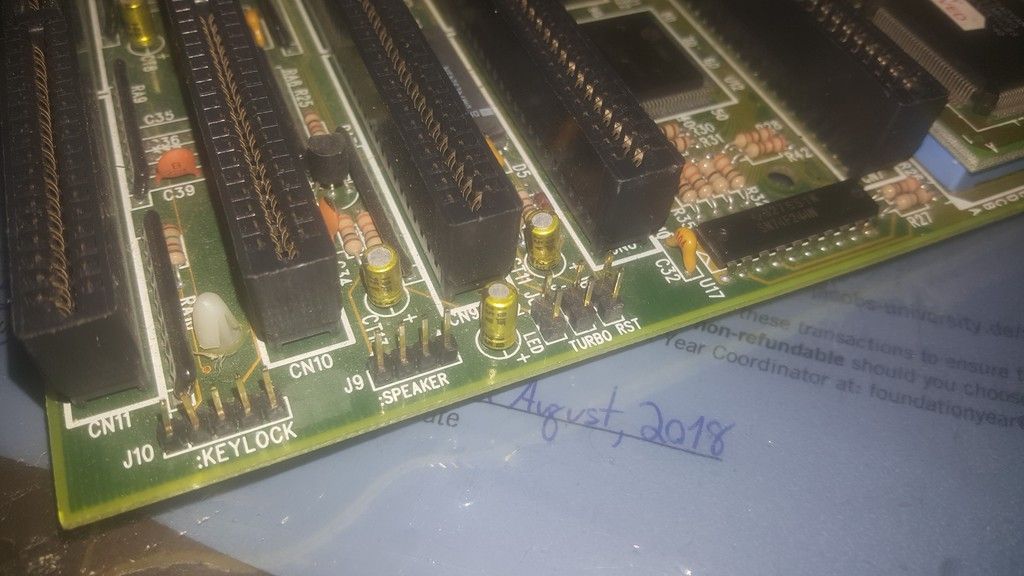
JidaiGeki wrote:Just needs to be configured using the jumpers, and you'll need to figure out the Turbo switch and power headers (and turbo LED connector if applicable). You might have a two-pin connector coming off one of the Molex connectors that used to be attached to this TD-52 front panel, if it's the original power supply.
Have a look through the examples on this page for a better understanding of how to set it up:
http://www.minuszerodegrees.net/led_speed_dis … eed_display.htm
PARKE wrote:Despite the fact that the turbo button works, and the system responds to its actuation, the other lead coming out the other side […]
Show full quote
Despite the fact that the turbo button works, and the system responds to its actuation, the other lead coming out the other side of the turbo button, which I assume is designed to hook into the LED display, does nothing to make the LED display light up.
>>
>>
Normally you have three connections on these displays:
power in from the motherboard or PSU,
turbo on-off in from the turbo switch,
power out to the turbo led.
Have you tried the power out plug to turbo led in both positions ? - these connections have a plus and a minus and sometimes it only works in one position.
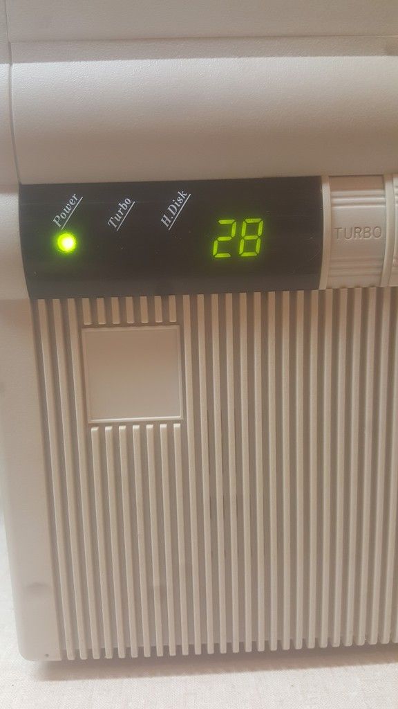
I do indeed have the working original power supply (a Latintech 235 watt) installed in the system. Tucked deep inside of the hard drive bay, with the twist tie still tied around the lead, was the two pin power cable you two had mentioned. It looks like my grandfather was never interested in that aspect of his machine! This is not super surprising, as he was using this 386DX40 into the late 90s, and I suspect he wasn't trying to get ancient software running. I untied the two pin cable, and gave power to the LED display; then I found the place where the turbo button hooks into it to actuate the change in display, and then finally I got to work on configuring the jumpers.
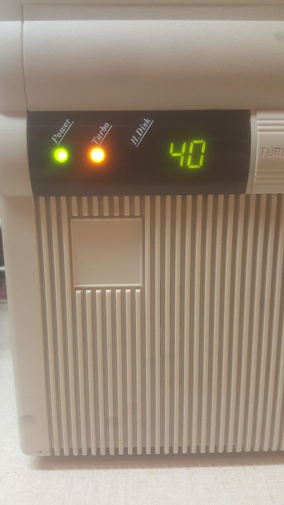
Even though I thought that each bar should be able to be set independently, it seems that not all combinations are possible (Or maybe I'm just a massive idiot). I settled with 40 and 28 respectively, as this is pretty close to what the computer actually runs at. My computer seems to be of the "Turbo actually is the faster setting" persuasion, and the Turbo LED is lit when the computer is running its fastest, not when the button is depressed, and the computer is running slower. I was under the impression that it was usually the opposite?
I did not know that old motherboards have a power out sometimes, I'll have to check and see if either his original board or this new board that I bought have a connector like that. It appears so far that neither do, so it makes sense that the power supply came with one installed.
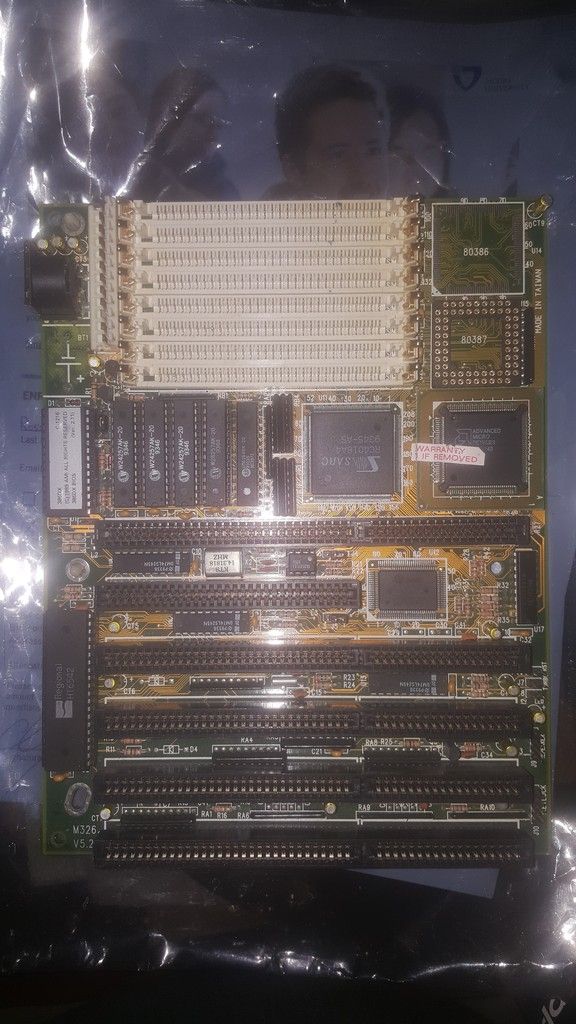
The motherboards are both numbered as shown below, the naming convention means nothing to me, I don't even know which company made them. It appears they're both from the same place, but maybe they're just both generics of the same design? The M326 had a poorly done sticker labeled "Toshiba CHIP 2, TC6154HS, Japan" covering the SARC 4018A4 to the left of the 386DX-40.
The original I pulled due to battery corrosion is labeled: M326 V5.2 and was produced in January of 1994
It is obviously a late 386 board, and a budget one at that, as its only got 6 ISA slots, 5 of them being 16 bit, one being 8 bit
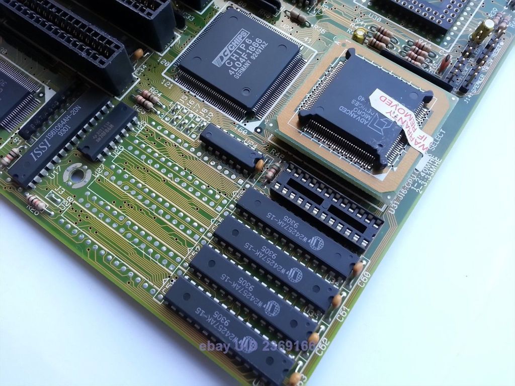
The replacement I ordered, which was the closet I could find worldwide for sale at the time of my search, is labeled: M321 V2.6 and was produced in 1992
Though I wish I was able to find an exact match for the original board, I am really in love with this pretty little thing. It has 6 ISA 16 bit slots, and 2 ISA 8 bits. The overall quality of the materials seems much higher than in the later board, and in general its a pleasure to work on (aside from the gold RAM retaining fingers going a little soft over the years.)
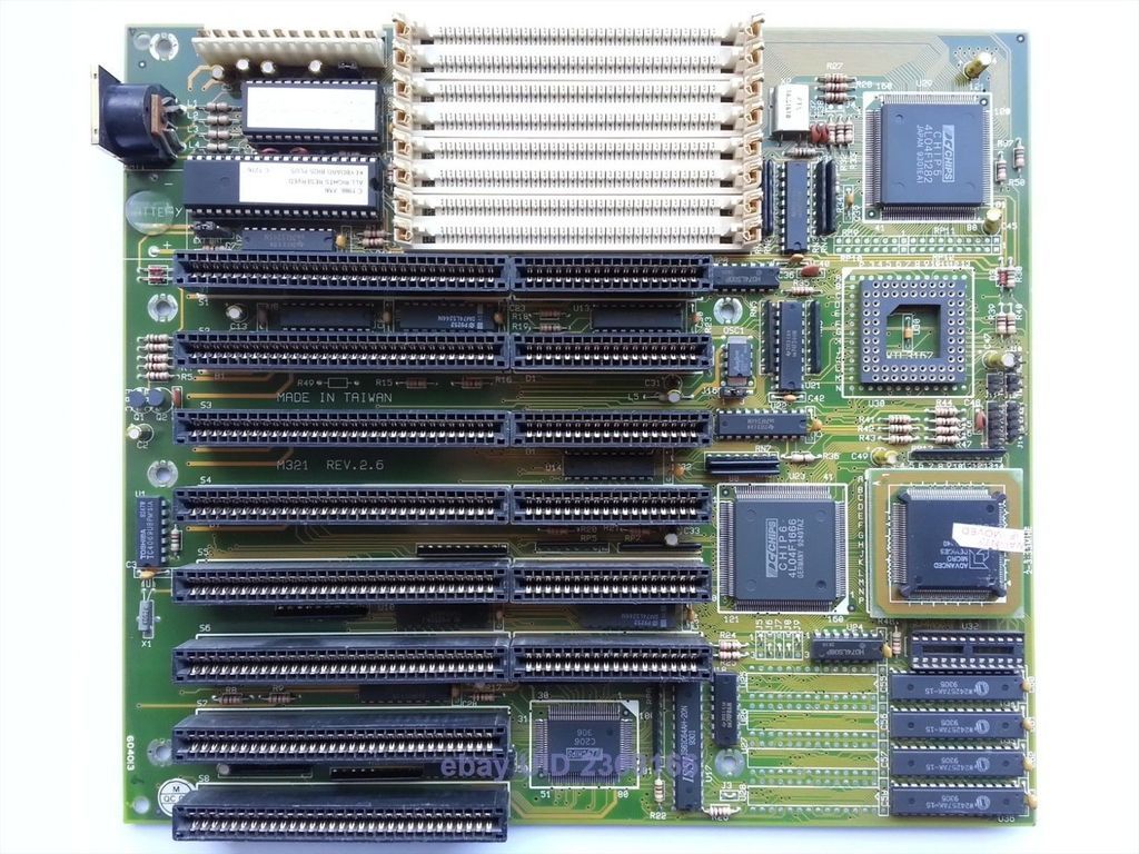
Despite their difference in quality, I imagine the boards would have ran about the same, especially seeing as they both have the same bios!
Thanks for all the help on this
Alex