Reply 20 of 38, by douglar

Rank
Oldbie
- Rank
- Oldbie
The boards with a single regulator have some PCB differences. Looks like I'm going to have to learn more about circuits before I do this.
The boards with a single regulator have some PCB differences. Looks like I'm going to have to learn more about circuits before I do this.
Very well done soldering clean up, what tools you used for this? Show your soldering station and vacuum solder sucker tool (photos would be good).
I'm working on getting good tools too.
Cheers,
Great Northern aka Canada.
Deksor wrote on 2018-09-14, 18:08:Well it looks new to me : no vrm.jpg […]
Well it looks new to me :
no vrm.jpgand here's how it was before
no vrm.jpgThe only thing I could think of that might have broken it (even though I kinda doubt it) is that the middle pin was harder to solder because there's much more copper to heat up in that area, but I already installed the heatsink with some solder paste, so the heat was already being dissipated, and I didn't leave the solder tip for more than 10-15s.
There's not much more missing components except "Q4" and "Q5" that are useless if "Q6" (the present regulator) is installed, and some CMS nearby the VLB slots and in the socket that seem to have nothing to do with the CPU voltage (I checked for continuity with my multimeter which gave me hundreds of ohms with anything related to the regulator, and voltages once the mobo was being powered on and that gave me 5V and 12V)
My only bets so far are either my regulator is fake, broken, or is the wrong one
(let me some more time to retrieve older pictures of the board, before and during the other mods, etc)
Edit : well I don't see any hardwired jumpers. There was some before, but these were used to control the cache as far as I know
I would say its a fake one / relabeled one.. Never seen such a VRM LT one which such a white and bright amature labeled marked one. Probably its better to look for an old stock one which certainly would be not fake.
~ At least it can do black and white~
Deksor wrote on 2018-09-14, 18:27:I get 5V on that trace. I've read the datasheet as well, it's kinda weird indeed, I'm not sure if the documentation is flipped o […]
I get 5V on that trace. I've read the datasheet as well, it's kinda weird indeed, I'm not sure if the documentation is flipped or if there's something else wrong there (Wrong regulator recommended on elhvb ?)
Edit : well, looking at that blurry picture Bought these (retro) hardware today, the regulator seems to be in the other orientation ... That's odd, but that would somewhat explain why ?
Though this is another revision of the board so I have no idea ...
Edit 2: After checking for continuity, the 1st pin seems to be connected to +5V indeed, but the 3rd one don't seem to be connected to the main GND.
I might try flipping that regulator, hoping it's the right thing to do and if so, that it didn't break ! But if so, why did the manufacturer did put "1" on the pin the nearest to the edge if that's the other way around :'(
Sometime it happens that the front of the VRM facing the bottom (on the motherboard) And the VRM heatsink pointing down.. Seen it on some 486 motherboard. Just check which pin needs to the right hole. If thats the case, then its the case.
~ At least it can do black and white~
douglar wrote on 2020-12-20, 18:32:Nicely done. You inspired me. […]
Nicely done. You inspired me.
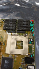
Here's a close up of my shuttle Hot 419 without 3.3v:
shuttle_hot-419_r1.jpgHere's a closeup of a board with 3.3v:
shuttle_hot-419_dz_r2.jpgI see a transistor, 2 added capacitors, 2 upgraded capacitors, 2 regulators, a bunch of jumpers, 8 resistors and a ferrite.
There's another pair of upgraded capacitors on the other side of the socket.
Seems daunting.
I can take a pretty good guess at the resistors from the stripes, but I'm not sure what to do with the capacitors or transistor without finding someone that has a board with the parts.
Iam guessing that the capacitors inside the socket are the same as the one on the input voltage lines of the motherboard. I thought those are 10uF @ 16 volt? tantalum.
~ At least it can do black and white~
Hello all
My first post here.
I have purchased a SIS 486G board as discussed in this forum. It was sold as "not working" - it's just to kill time in lockdown!
I have a question and I hope you can help me: there are no voltage regulators on my board so shall I assume it's a 5V-only board? From the datasheet I found online it should do 3.3/5V. I can replace the missing regulator of course - and thanks for sharing all the info. The motherboard itself says 3.3/5V!
One other thing, all the cache chips are 28 pins but the sockets are 32 pins. Is that supposed to be like that??
My Youtube channel: https://www.youtube.com/@tony359
Sure you can put a 3.3V regulator there, look at my posts ^^
For the cache, this is perfectly normal. 28 pin chips are simply smaller in capacity (256kilobits each). Bigger chips can hold 512 or 1024 kilobits for a total of 512KB or 1MB of cache.
Trying to identify old hardware ? Visit The retro web - Project's thread The Retro Web project - a stason.org/TH99 alternative
Thank you Deksor - I shall do and thanks for taking the time to document this.
I was just a bit puzzled as the board says on the PCB 3.3V but then it doesn't do that? 😀
Anyways, I have tested VCC and indeed I don't get anything with the jumpers set to 3.3V. However, some pins do receive 5V (not VCC ones) - is that normal?
Oh, one more question - a bit OT: what speed should I set on this board to work with my DX4/100? I see there are 100Mhz supported on the specs but the jumper settings only get up to 66Mhz - apologies if this is a silly question, last time I saw a 486 was 25 years ago!!
I have dumped the BIOS - it's attached for future reference!
My Youtube channel: https://www.youtube.com/@tony359
Are either of these your boards? There's links to manuals with the jumper settings on those pages.
http://www.win3x.org/uh19/motherboard/show/5549
http://www.win3x.org/uh19/motherboard/show/5666
Sometimes if you have a cutdown version of the board or an odd revision, you might need to go hunting for a while.
I was messing around with a similar issue yesterday. I gave up on the idea of putting the 3.3v components on my board because there were just too many differences between the different revisions of the board. I lucked into a free evergreen upgrade chip that had a built in 5v to 3.3v adapter and was playing around with that, but the board was not detecting the CPU correctly. The bios said Dx4 100, but everything in DOS said it was running at 133mhz. The speedsys CPU rating was 42, which was about 20% low.
I tried MR bios for my Opti 895 chipset. I could get into the bios set up, but things were not right and it was never close to booting.
Then I found a new bios & manual on vogondrivers.com. Manual was still a little off, but it was a lot closer to my revision of the board.
The new bios correctly identified my chip. The new manual showed me how to jumper the board for AMD 5x86 chips and how to enable P24D features. That bumped the speedsys CPU rating up to 48. Enabling the write back cache in the bios took it to 50. Great success!!!
The new bios also supported larger & faster IDE drives, which is also very nice. Maybe I'll try pushing it to 160mhz at some point down the road.
Hi Douglar
I found the info here: https://www.elhvb.com/webhq/models/486vlb3/sis486ge.html
The model number matches and I had no issues identifying all the jumpers. I hope the regulator is all it needs. Again, what puzzles me is that the PCB says 5V/3.3V but then the 3.3 regulator is missing. Indeed when I set the jumpers to 3.3V I have no VCC on the socket. Now waiting for the regulator to arrive 😀
My Youtube channel: https://www.youtube.com/@tony359
tony359 wrote on 2021-02-07, 19:17:Hi Douglar
I found the info here: https://www.elhvb.com/webhq/models/486vlb3/sis486ge.html
The model number matches and I had no issues identifying all the jumpers. I hope the regulator is all it needs. Again, what puzzles me is that the PCB says 5V/3.3V but then the 3.3 regulator is missing. Indeed when I set the jumpers to 3.3V I have no VCC on the socket. Now waiting for the regulator to arrive 😀
They just used the same Circuit boards on the retail boards that had support of 3.3 volt processors as for the low cost OEM boards that didnt had the possibility to use the 3.3 volt option, so they left these components away.
And if you used the same circuit boards, then you didnt had to design a new one. This all to reduce the costs.
It was harder to upgrade the OEM ones.. Some company `s dont want to let you upgrade the current boards. (they would put a sticker on the spot of the VRM, when tempering with it should void your warrentee) Because they most likely would you rather sold you a new one ..
~ At least it can do black and white~
I see, thanks! Well, I hope the regulator is all that is missing. I do have 5V as input so hopefully the output then goes to the VCC pins. I do see some resistors on the ADJ pin so hopefully that will work.
Edit: yes, the regulator output is connected to the voltage selection jumper and from the jumper straight to the CPU. Good times when you did not need stupid power and massive regulations for a CPU!!! 😁
Again, is it ok to see 5V on some other pins of the socket? I did not write down what those pins were but they were not VCC.
My Youtube channel: https://www.youtube.com/@tony359
Update - I couldn't wait so I plugged my bench PSU on the CPU voltage pins (the jumpers on the MB) and gave those 3.3V - the PSU is fully floating so it was safe to use.
And it works! the MB was sold as "not working". I washed it and re-seated everything but also went through all the jumpers which were - IMHO - incorrectly set. Anyways, I have a working system! I should get the regulator soon so I can get rid of the external PSU! 😀
My Youtube channel: https://www.youtube.com/@tony359
Thanks for the BIOS upload !
Unfortunately it's the exact same one as the one that someone else sent to me a while ago. I don't know what is the difference between both ... Oh well. I'm really curious to see how's the AMI bios like though
Trying to identify old hardware ? Visit The retro web - Project's thread The Retro Web project - a stason.org/TH99 alternative
Update
I have installed the regulator and it works like a charm with no modifications required. The board works fine. I will add a heatsink but it gets barely warm.
Thank you for the massive help!
My Youtube channel: https://www.youtube.com/@tony359
How do you know it works ? Did you test the voltage in the socket ?
You have to configure the board for 3.3v operation
Trying to identify old hardware ? Visit The retro web - Project's thread The Retro Web project - a stason.org/TH99 alternative
Ehm... I know it works because it boots up? 😀
Yes, I did check the voltages before fitting the CPU back and I have 3.34V in the socket. Then I booted up without the external PSU (and the jumpers set to 3.3V indeed) and it's working fine.
Am I missing something? 😀 I do not have a keyboard yet so I cannot go past the BIOS but I will fit a heatsink anyways.
My Youtube channel: https://www.youtube.com/@tony359
I was afraid you just installed the VRM without checking the voltage and changing the configuration. 3.3V 486s can survive for a while at 5V, that's why. But everything's allright since you checked everything ^^
Trying to identify old hardware ? Visit The retro web - Project's thread The Retro Web project - a stason.org/TH99 alternative
Ah, I see! Thanks for asking! Everything is ok - only thing is that the MB fails to boot when cold - and every now and then. I'm trying to identify what the problem is.
Did I see on this thread that it is OK for that motherboard to recognise my DX4/100 as "DX4-S 100Mhz"?
My Youtube channel: https://www.youtube.com/@tony359