VOGONS


First post, by GabrielKnight123

User metadata
Rank Oldbie
Rank
Oldbie

I have grinded away to the pins of a Dallas DS12887A RTC for pins 16 and 20 for a button battery replacement and I know I have to separate the small thin wire going to the battery on pin 16 but do I have to do the same for pin 20? Here is a pic of what I have:

RTC%20Fix_zpski0slxuy.jpg

I have not cut any of the "wires" yet but I just wanted to make sure I was doing this right before I cut anything. The pic below shows where I think gets cut.

Cut_zps5pkqotib.jpg

Reply 2 of 18, by GabrielKnight123

User metadata
Rank Oldbie
Rank
Oldbie

I have found out that I cant put a button battery holder on top of the RTC as there is no room from other parts in the way so I am going to use wires to goto an external battery but I already have one made that I can use but it has 3x AAA batteries so that would be 4.5 volts ~ is it safe to use 4.5 volts or should I use 3 volts maybe because of some reason to do with the RTC not blowing up from to much voltage?

Reply 3 of 18, by realoldguy23

User metadata
Rank Newbie
Rank
Newbie

It could work with 4.5V as well. The CMOS clock chip itself is most probably a standard one that can take up to 5V. But why taking chances? Just short the contacts for one cell in your 3xAAA battery holder and put just two AAA cells in.

Reply 5 of 18, by GabrielKnight123

User metadata
Rank Oldbie
Rank
Oldbie

Well I must of did something wrong as the old RTC chip i modded didnt work and now wont boot with it, the new RTC I have I also grinded away but this time I didnt cut the lines and I tested the voltage from the exposed pins and it has 3 volts but when I use it in the motherboard it still wont save bios settings and time/date so im guessing something else is faulty but I dont know - what do you guys think. Im not seeing the message at post about a bad cmos error the one that points to the battery in any system so could it be somewhere else?

Reply 6 of 18, by realoldguy23

User metadata
Rank Newbie
Rank
Newbie

Maybe it is about time you give more information about the board and a few pictures of the chip in the board, boot screen, etc... Could be that you damaged the original chip and the replacement is not conpatible. Is the replacement one exactly matching the type of the original?

Reply 7 of 18, by GabrielKnight123

User metadata
Rank Oldbie
Rank
Oldbie

Ok thanks realoldguy23 here's what I know about the motherboard, its a GA-586HX Rev 1.56, the old dallas RTC was "Dallas DS12887A" and the new chip is a "Dallas DS12887A+" I asked about the difference with the plus version and someone said the plus version is just the lead-free version and that its the same, under the RTC on the motherboard is written "ALIM5818" and on the Bios chip is:

Award software inc. 1995
all rights reserved
PCI/PNP 586
S/N: 071989070

I took some pictures here:
http://s836.photobucket.com/user/sierragames/ … rary/GA%20586HX
The picture I took of the Bios screen Is just there to show the Bios version

When it boots there is no message about a low battery or bad checksum and if I change anything in the bios then reboot the settings are lost.

Reply 8 of 18, by realoldguy23

User metadata
Rank Newbie
Rank
Newbie
GabrielKnight123 wrote:

I asked about the difference with the plus version and someone said the plus version is just the lead-free version and that its the same

Yes, this seems to be correct. I checked the datasheet from Maxim (who obviously bought DALLAS at some point) and it states exactly this.

While checking the datasheet I also noticed that the battery-less DALLAS 12885 is designed for a VBAT between a minimum of 2.0V and a maximum of 4.0V. Your 3x AAA battery pack would exceed this limit, although I think it would probably still work. Anyway, if you indeed connected a 4.5V battery pack, you should try to remove one AAA battery as described above.

The space is really tight around the RTC on your MB. You should check if you have shortened the solder joints to the case by accident. (BTW, if you shortened the solder joints to the heat sink of the linear regulator you have put in the RTC chip the wrong way.) Measuring the battery voltage when it is built in is in general a good idea. You would notice a short immediately.

What does the BIOS exactly say when you start up?

I did the same RTC battery replacement on an ODIN12C887A for my Biostar board (Socket 7 from around the same time). This has an AMI BIOS, which didn't even boot the OS because it always said "CMOS battery low - press F1 to enter setup". Stupid thing.

Reply 9 of 18, by GabrielKnight123

User metadata
Rank Oldbie
Rank
Oldbie

The RTC chip socket was soldered into the motherboard when I got the motherboard and the underside looks like a professional job or it looks good enough to be done by the manufacture of the motherboard company, Im not sure why the original RTC stopped working but it might have been from connecting the 4.5 volt battery pack so mental note to self try 2x AAA first 🙁. When the PC boots all there is for the post is the same as the two pictures I linked above so there is no message about low battery or bad checksum. What else is required in terms of hardware to keep Bios settings alive?

Reply 10 of 18, by realoldguy23

User metadata
Rank Newbie
Rank
Newbie

No, I meant that the solder joints where you soldered the wires for the battery on the chip case itself might shorten to the case because the chip is so close to the edge of the board. I think the board itself might be good. It doesn't look damaged at all.

To make sure I fully understand, if you start the board after it was disconnected from the power you get a CMOS checksum error. You then correct the CMOS settings. Are they wrong/reset to default when you enter the Setup in this case? Subsequent restarts without disconnecting the power are successful, i.e. no error message until you disconnect and reconnect the power?

Just a guess, but there are 12887 and 12C887. The difference is that the "C" version declares a RAM cell as "century" byte for the clock that the "non-C" version uses as general purpose RAM. The chip on the pictures of your MB is clearly a "non-C" version. Maybe the one you got from Ebay is wrongly marked or a faked version?

Maybe you should consider to get a brandnew chip from an electronics distributor. You should check Mouser or Digikey. Reichelt.de in Germany has them in stock: 12887 for 12.70€ and 12C887 for 10.30€

Reply 11 of 18, by GabrielKnight123

User metadata
Rank Oldbie
Rank
Oldbie

Ah I get you now realoldguy23 but when I did all this testing the motherboard was out of the case and on a wooden table and the two wires that were soldered to the chip were protected with hot glue.

"To make sure I fully understand, if you start the board after it was disconnected from the power you get a CMOS checksum error."
No I dont get an error at all

"You then correct the CMOS settings. Are they wrong/reset to default when you enter the Setup in this case?"
They then reset to default

"Subsequent restarts without disconnecting the power are successful, i.e. no error message"
No it still resets to default with no error messages

"until you disconnect and reconnect the power?"
This will reset the settings too with no error messages.

"Just a guess, but there are 12887 and 12C887. The difference is that the "C" version declares a RAM cell as "century" byte for the clock that the "non-C" version uses as general purpose RAM. The chip on the pictures of your MB is clearly a "non-C" version. Maybe the one you got from Ebay is wrongly marked or a faked version?"
I didnt go the ebay route as I wanted a new one so I bought this one from "RS" here:
https://au.rs-online.com/web/p/real-time-clocks/7327309/

"Maybe you should consider to get a brandnew chip from an electronics distributor. You should check Mouser or Digikey. Reichelt.de in Germany has them in stock: 12887 for 12.70€ and 12C887 for 10.30€"
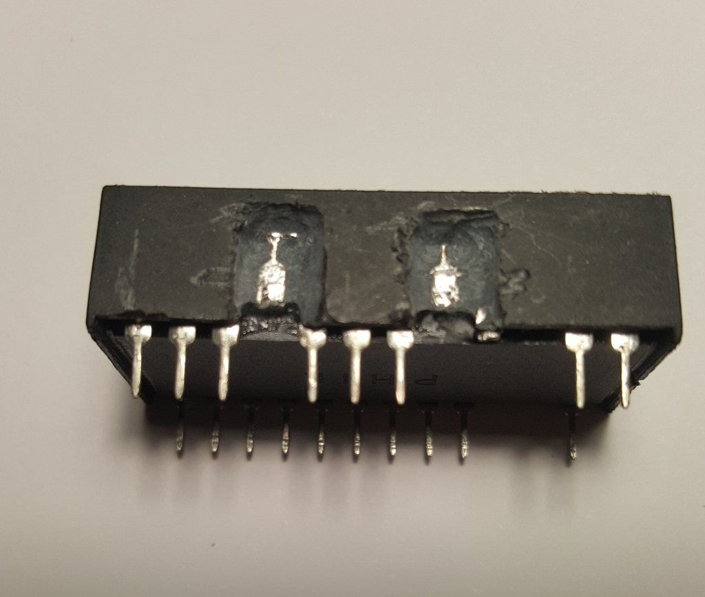
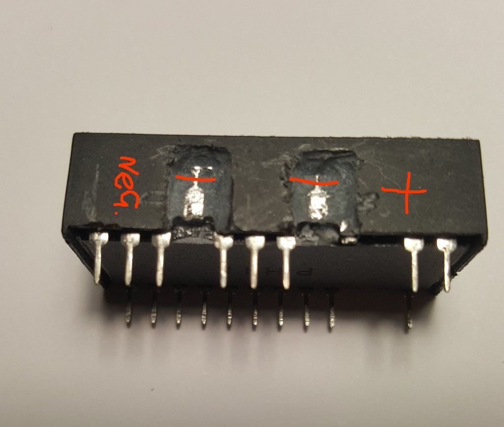
Im hoping RS sold me a good one but I will try and buy another DS12887A chip with a dead battery but this time not supplying it with 4.5 volts as I found that there was a difference in the internal pin size on pins 16 and 20 when grinding at the chip case but this does not explain why there are no error messages about the battery and settings not being saved.

Reply 13 of 18, by realoldguy23

User metadata
Rank Newbie
Rank
Newbie

Yes, good idea. If this jumper would be set it would behave exactly like that. And the funny thing is the /RCLR pin is the pin 21 on the RTC chip, so just adjacent to the pin 20 for VBAT. You should check with a multimeter if pin 21 on the IC socket on the board is somehow shorted to GND. Shorting it to VBAT could also lead to strange behavior I guess, although it is low-active.

Reply 14 of 18, by GabrielKnight123

User metadata
Rank Oldbie
Rank
Oldbie

I checked the chip outside of the motherboard and pin 21 (/RCLR) is not getting any voltage when checked with a multi meter from pin 20 (positive) but I do see that pin 21 is there but on the original RTC I had pin 21 is not there it has been removed. I am also getting voltage from:

pin 20 (+) and:
pin 16 (-)
pin 24 (vcc)
pin 12 (ground)
pin 1 (mot)

What do you think should I try and remove pin 21 or is it there for a reason

Reply 15 of 18, by realoldguy23

User metadata
Rank Newbie
Rank
Newbie

I think if you remove pin 21 from your new RTC you can be sure that the it is not cleared automatically anymore.

Does your multimeter have a continuity tester? Check if there is continuity between the RTC socket's pin 21 and GND on the RTC socket's pin 12. You can also use the resistance measurement of the multimeter. It should show infinite or unconnected between pin 21 and pin 12 of the socket. If not, we've found the root cause.

Reply 16 of 18, by GabrielKnight123

User metadata
Rank Oldbie
Rank
Oldbie

I think you're right too realoldguy23 I did some reading and found this:

in the pin out manual here:

https://datasheets.maximintegrated.com/en/ds/ … 5-DS12C887A.pdf

it says:

N.C. No Connection. This pin should remain unconnected. Pin 21 is RCLR for the
DS12887A/DS12C887A. On the EDIP, these pins are missing by design.

and:

RCLR
Active-Low RAM Clear. The RCLR pin is used to clear (set to logic 1) all the
general-purpose RAM, but does not affect the RAM associated with the RTC. To
clear the RAM, RCLR must be forced to an input logic 0 during battery-backup
mode when VCC is not applied. The RCLR function is designed to be used
through a human interface (shorting to ground manually or by a switch) and not
to be driven with external buffers. This pin is internally pulled up. Do not use an
external pullup resistor on this pin.

Im just now going to check continuity from your idea on pins 21 and 12, be back soon

Reply 17 of 18, by GabrielKnight123

User metadata
Rank Oldbie
Rank
Oldbie

Eureka !!!!!!!!!!!!!!!!!!!!!!!!!!!!!!! It worked 😀 the only thing I was worried about was using the dremel to grind off the rest of the leg from the part that twisted off because in the pin out doc above it says something about vibration and the crystal can get damaged. Thanks realoldguy23 you were very helpful.