VOGONS


First post, by feipoa

User metadata
Rank l33t++
Rank
l33t++

Does anyone have an DataExpert ExpertBoard EXP4349 motherboard which contains the 3.3 V regulator for later 486 CPUs? The manual mentions this (see attached manual), but I only see what appears to be solder vias for a voltage regulator. Anyone know the part number for this voltage regulator?

Filename
DataExpert_ExpertBoard_EXP4349_Users_Manual.pdf
File size
668.73 KiB
Downloads
59 downloads
File license
Fair use/fair dealing exception
EXP4349.jpg
Filename
EXP4349.jpg
File size
1.98 MiB
Views
1253 views
File license
Fair use/fair dealing exception

Plan your life wisely, you'll be dead before you know it.

Reply 1 of 25, by The Serpent Rider

User metadata
Rank l33t++
Rank
l33t++

I guess the voltage regulator from Dataexpert EXP4045 can be used.

I must be some kind of standard: the anonymous gangbanger of the 21st century.

Reply 2 of 25, by feipoa

User metadata
Rank l33t++
Rank
l33t++

I'm looking for the easy way out - a part number. Otherwise, I'll have to determine the in, out, gnd, and vadj for these 3 possible solder pads and select my own VRM. One set of solder pads is 3-pin, the other is 4-pin, and one more is 5-pin. Looks to me like they were really wanting to leave themselves a lot of options. Curious that I don't see more empty resistor solder pads. Perhaps the resistors were put in, just not the regulator. Regulators must have been relatively expensive.

Plan your life wisely, you'll be dead before you know it.

Reply 3 of 25, by stamasd

User metadata
Rank l33t
Rank
l33t

I don't know the exact part number for this particular motherboard, but many 486-era motherboards that I've seen seem to use VRMs from the LT1086 series http://www.analog.com/media/en/technical-docu … ets/1086ffs.pdf in particular the adjustable one LT1086CT.
Sometimes they use similar LT1085 parts instead which are rated for higher current (3A for 1085 vs 1.5A for the 1086) http://www.analog.com/media/en/technical-docu … ts/108345fh.pdf

Modern equivalents (pin-compatible) are LM350 (3A) and LM338 (5A).
http://www.ti.com/lit/ds/snvs772b/snvs772b.pdf
http://www.ti.com/lit/ds/symlink/lm338.pdf

I/O, I/O,
It's off to disk I go,
With a bit and a byte
And a read and a write,
I/O, I/O

Reply 4 of 25, by feipoa

User metadata
Rank l33t++
Rank
l33t++

Unfortunately, I've seen such a variety of pin outs on VRMs that I'd still have to do some measurements to determine the proper pin configuration. I have another 386 board, which uses a 486 chipset, that implemented a DIP VRM what I haven't seen much of.

Plan your life wisely, you'll be dead before you know it.

Reply 7 of 25, by feipoa

User metadata
Rank l33t++
Rank
l33t++
BastlerMike wrote:

I have this board with regulator installed. Will have a look later

Fantastic! Can you also take a photo so I know which of the 3 groups of solder pads to use and what orientation the VRM is in?

EDIT: What BIOS is on your board? Award, Phoenix, AMI?

Plan your life wisely, you'll be dead before you know it.

Reply 8 of 25, by BastlerMike

User metadata
Rank Member
Rank
Member

If I remember correctly, the pinout of the 3-terminal solder place was inverted, what means that the regulator is to be soldered on the backside of the board. After some measuring it was decided to solder the IC in the shown way. All this was done years ago, so I'm no more familiar with the details but I think instead of LT1584 any LT108x should also work. My board has an AMI bios installed

Attachments

  • 20181015_152705.jpg
    Filename
    20181015_152705.jpg
    File size
    504.66 KiB
    Views
    1147 views
    File license
    Fair use/fair dealing exception

Reply 9 of 25, by stamasd

User metadata
Rank l33t
Rank
l33t

The LT1584 is a 7A part, much higher rating than the 108x and higher than even the LM338 which goes to 5A. I don't know if that much current capability is required, IMO a LM338 would work fine and it's cheap, easy to find and pin compatible.
The only other LDO VRM that's pin compatible with the 1584 and has the same current capability is the LT1580; there are others of 7A and above but they're not pin-compatible.

I/O, I/O,
It's off to disk I go,
With a bit and a byte
And a read and a write,
I/O, I/O

Reply 10 of 25, by feipoa

User metadata
Rank l33t++
Rank
l33t++

BastlerMike. OK, so your board didn't naturally come with that LT1584, that is, you added it later and don't recall how you arrived at this part number?

7 A is way overkill. I've seen Am5x86-133 interposer boards with 1 A VRMs.

I haven't yet looked at datasheets, but you're saying that the the 1085 has the same pinout as this 1584? I'm sure I have some NIB 1085 or 1086 regulators. It would be nice not to have to bend the pin like that. Knowing me, I'll probably check all pinouts and see if one of the 3 other solder positions will be more suitable.

BastlerMike: Were there any resistors you needed to add? If so, which? Did you check the output? Is it 3.30 V?

Plan your life wisely, you'll be dead before you know it.

Reply 11 of 25, by stamasd

User metadata
Rank l33t
Rank
l33t

All of these regulators 108x, 158x, LM350, LM338 have the same pinout and the same application circuit. The only difference between them is how much current they can deliver.

The other solder pads are probably for other types of regulators. I think I saw one with 5 positions, there are other kinds of regulators with 5 pins but they're not exactly direct replacements for the above.

I/O, I/O,
It's off to disk I go,
With a bit and a byte
And a read and a write,
I/O, I/O

Reply 12 of 25, by feipoa

User metadata
Rank l33t++
Rank
l33t++

For linear regulators for which I have labelled, I have LMS1585ACSX-ADJ, LD1084V, LD1085V, LM1085IT, LD1085D2M-R, MIC29302WT, LP38503TSX-ADJ, PQ30RV21, and PQ30RV31. I also have a bin of desoldered regulators. Some are 3-pin, some 4-pin, some 5-pin. Looks like I'm set for the mod.

Curious, though, if any boards came with the VRM in place from the factory, and if so what VRM they used. Would be nice to keep the board original, if possible. The pin bend-over shown by BastlerMike is probably not the original configuration.

Plan your life wisely, you'll be dead before you know it.

Reply 13 of 25, by feipoa

User metadata
Rank l33t++
Rank
l33t++

I decided to map out all 3 options for the VRM (attached) because I was determined to find a VRM in my bin which fit the default pin spacing. I ended up having several which had the same pinout, however Q48 and Q4A have a tighter pin spacing than the units I had. I found one which fit Q4, however testing on a breadboard revealed the that VRM was dead. I have one VRM with tight spacing that would fit Q4A, MIC29302, however I wanted to save that for the SXL2-66 proto board. Alas, I ended up doing what BastlerMike did by forcing the spacing on a 3-pin 1587 VRM. 1587 is 3A max.

Under no load, I measured 3.445 V from the VRM. At load, I'm guessing 3.41 V. This is better than 3.3 V for a broader CPU selection range. I've had some Cyrix 5x86 chips not work at 3.3 V.

EXP4349_VRM_pinouts.jpg
Filename
EXP4349_VRM_pinouts.jpg
File size
175.91 KiB
Views
1089 views
File license
Fair use/fair dealing exception
EXP4349_VRM_1587.jpg
Filename
EXP4349_VRM_1587.jpg
File size
270.72 KiB
Views
1089 views
File license
Fair use/fair dealing exception

Plan your life wisely, you'll be dead before you know it.

Reply 15 of 25, by BastlerMike

User metadata
Rank Member
Rank
Member

Thank you for your investigations and drawings. I remembered right, that the Q4 position does not match the pinout of most of the usual 3-terminal regulators.
Furthermore I have to correct the fact that the Bios is not an AMI but a Phoenix.

Reply 16 of 25, by feipoa

User metadata
Rank l33t++
Rank
l33t++

I'm going to try it without a heatsink first and measure the temperature. I see many 486 boards with linear regulators and no heatsink. On this particular board, the adjacent components make it so that I"d need to bend the VRM way down like BastlerMike, or have the heatsink rise up vertically quite a bit, making storage next to other motherboards problematic.

Plan your life wisely, you'll be dead before you know it.

Reply 17 of 25, by feipoa

User metadata
Rank l33t++
Rank
l33t++

BastlerMike, do you recall which CPUs you were using on this motherboard? I cannot seem to get the board working properly at 40 MHz. I am only able to get DLC/SXL CPUs running with a 25 or 33 MHz FSB. Also, when using an SXL2 with a 25 MHz FSB, after I enable clock doubling, the DOOM benchmark will crash a few seconds after loading. 1x at 25 MHz or 33 MHz work fine though. I'm wondering if my board is damaged or if this happens on other motherboards as well.

Plan your life wisely, you'll be dead before you know it.

Reply 18 of 25, by feipoa

User metadata
Rank l33t++
Rank
l33t++

I've attached some oscilloscope captures of CLK2 on this motherboard using a 486DLC at 25, 33, and 40 MHz. Notice how the voltage swing at 40 Mhz is noticeably smaller than even 33 MHz. I wonder if this is what is causing the board not to function well at 40 MHz? A 386/486 hybrid board demands a large frequency range from the clock generator, from 25 - 80 MHz.

At 40 MHz, perhaps with noise, some of the levels are being mistaken for high or low. If I recall right, crossing on the rising edge from 0 V to 5 V, above a level of 2.5 V is high, where as on the falling edge, dropping below 2.5 V is low. Perhaps some levels are being mistaken. Without adding an amplifier, how does one correct for this? I suspect reducing the 33-ohm series resistor might help.

Attachments

  • DLC-40.png
    Filename
    DLC-40.png
    File size
    6.45 KiB
    Views
    994 views
    File license
    Fair use/fair dealing exception
  • DLC-33.png
    Filename
    DLC-33.png
    File size
    7.06 KiB
    Views
    994 views
    File license
    Fair use/fair dealing exception
  • DLC-25.png
    Filename
    DLC-25.png
    File size
    7.67 KiB
    Views
    994 views
    File license
    Fair use/fair dealing exception

Plan your life wisely, you'll be dead before you know it.

Reply 19 of 25, by feipoa

User metadata
Rank l33t++
Rank
l33t++

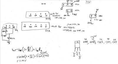
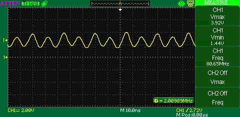
As expected, shunting the 33 ohm resistor increased the voltage swing at 40 MHz (attached), however, this didn't resolve the underlying problem of operation at 40 MHz.

The board eventually stopped booting, even at 33 MHz. It now spits out Phoenix code 60, which according to the POST card is "Extended memory test". Prior to that, it was hung on a code which I looked up to be chipset register configuration, or something along those lines.

All along, the board would not let me enter the BIOS at power-on, e.g. hit DEL for Setup. It simply ignored my command. The only means in which I could enter the BIOS was if I previously had soft reset the system (at which point hitting DEL would enter Setup) or if I swapped out the BIOS chip for the AMI variant - let it checksum error, then put the Phoenix back in. A very odd issue I haven't encountered before. Before the board died, it was hanging on boot and loading default settings.

At the start of testing, the 3.6V PGA-168 SXL2-66 would at least POST, but over time, it wouldn't work at all. Only the 5V PGA-168/132 SXL's would work properly in the end, that is, to boot into Win3.11 and load IE5 w/google search page.

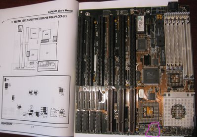
Even when I first tested the board, I tried 40 MHz, and it wouldn't boot. So from the onset, something was amiss. Based on warranty stickers with a google image search, I see that this board was offered with a SXL-40, so 40 MHz presumably was feasible. Were some of these ALi 1429G chipsets not qualified for 40 MHz, as was the case with some older CHIPS 386 chipsets? Seems that it would have the speed stamped on the chipset if that was the case.

I paid $60 for this board plus $18 shipping from Russia. It took 2+ months to arrive and I don't think it was wrapped in an anti-static bag. Item condition was only dashes -- with seller notes "not tested". Did I receive someone else's known lemon, or are all these boards wonky with 40 MHz and SCSI? Did the seller know he was selling a lemon? This is a question I've asked myself in the past when receiving faulty items. Looking at other items the seller has available, I see that some are "tested working" and others are "not tested". I have a feeling that "not tested" means "tested, not working, but don't want to scare off the buyers, so I'm omitting information"

Attachments

  • DLC-40_0ohm.png
    Filename
    DLC-40_0ohm.png
    File size
    7.04 KiB
    Views
    975 views
    File license
    Fair use/fair dealing exception

Plan your life wisely, you'll be dead before you know it.