First post, by Baoran
Rank
l33t
Does anyone know how to configure this kind of lcd case display?
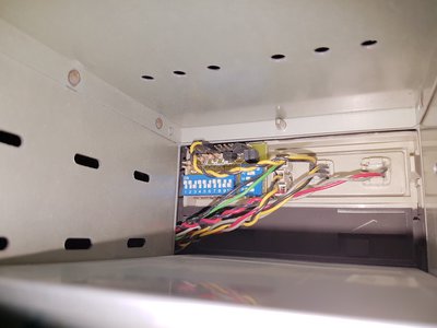
Does anyone know how to configure this kind of lcd case display?
Trial-and-error ought to work well enough, wouldn't you think?
Especially as this one has dip-switches; many of them stuck to motherboard-style jumper blocks.
Dip switches! How luxurious.
Yep you won't break anything, just toggle away until it displays what you want it to say. Hey that was quite poetic.
Life? Don't talk to me about life.
there is 14 sections in a 2 digit lcd screen, but there are 15 dip switches there. Any idea what the 15th is for?
wrote:there is 14 sections in a 2 digit lcd screen, but there are 15 dip switches there. Any idea what the 15th is for?
decimal point?
I did put a motherboard to the case and I got the turbo button and turbo led to work, but I don't know how to even get that lcd to even power up. Perhaps the wires coming from the turbo button are connected wrong or something?
Is it connected to the PSU? A lot of AT PSUs had the little black and red wired plug included but if not then you can add one yourself or buy an adapter.
Life? Don't talk to me about life.
wrote:Is it connected to the PSU? A lot of AT PSUs had the little black and red wired plug included but if not then you can add one yourself or buy an adapter.
There are lots of pins at top of it in the picture, where exactly I am suppose to connect psu to if I find one that has it?
Unfortunately the psu only has 3 molex, 2 floppy and motherboard connectors.
Can we get a better pic? I can't see the pins. Do any of them have a + / - ?
related:
Life? Don't talk to me about life.
wrote:Can we get a better pic? I can't see the pins. Do any of them have a + / - ?
related:
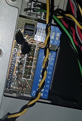
I meant those 9 pins in line above the dip switches where those yellow and black wires are connected that come from the turbo switch. I don't know if those wires are correctly connected because they were like that when I got the case. There are some markings but they are hard to see because of the resistors. Below 2 leftmost pins it says P.L and below that there are + and - signs. 2 nest pins say T.L and below that - and + signs.
It was very difficult to take picture of the markings, but I managed to take one that shows some of them.
I went through my stuff and I found this:
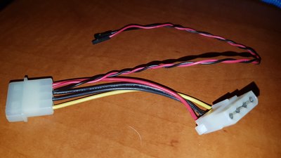
Anyone knows which pins I can connect it to get power without breaking anything?
Came up against a DIP switch MHz display in this build - Re: "Archmont" desktop 386DX-40 build
I'm going to guess yours will be a similar setup to mine, ie 5 switch bank will be for tens, and you will make numbers from segment combos. Your unit seems to have power input and switch/led headers marked up.
wrote:Came up against a DIP switch MHz display in this build - Re: "Archmont" desktop 386DX-40 build
I'm going to guess yours will be a similar setup to mine, ie 5 switch bank will be for tens, and you will make numbers from segment combos. Your unit seems to have power input and switch/led headers marked up.
But which header is which? Does P.L mean power led? T.L Turbo Led? What are rest of those symbols next to the pins?
wrote:Below 2 leftmost pins it says P.L and below that there are + and - signs. 2 nest pins say T.L and below that - and + signs.
PL stands for Power Led and TL stands for Turbo Led - you can use these pins to feed the frontpanel leds instead of connecting them to your motherboard.
The next three pins are usually for connecting to the turbo switch.
And the last two pins are then (as was pointed out already) to connect to 5volt.
I took a risk. I connected the power to P.L + and - and I have power now on the lcd.
It seems very limited what numbers can be shown on the lcd though unfortunately when I tried the dip switches.
In the bank of 10 switches first 7 seems to just change segments of second digit when turbo is on and switches 8-10 seems to change first digit between 1,2 and 3.
Bank of 5 switches just seem to change non-turbo mode between numbers 0, 2, 4, 6, 8, 10, 12, 14, 16 and 18
So unfortunately the highest number for turbo on seems to be 39 and highest for non-turbo seems to be 18. Unless those extra pins at the top do something about that. The right jumper turns of the display for non-turbo and left turns of the display for turbo mode.
Sounds a little odd. Are you sure combinations of dip switches don't add up in binary to make higher numbers?
wrote:Sounds a little odd. Are you sure combinations of dip switches don't add up in binary to make higher numbers?
This is my first time trying these lcd speed displays, so I can't be sure. I just don't know how it would make bigger numbers. Perhaps it was made in 286 era since the defaults when I turned on the power were 12 for turbo and 6 for non-turbo.