VOGONS


Battery shorting a motherboard?

Topic actions

First post, by obcbeatle

User metadata
Rank Newbie
Rank
Newbie

Hello ... this afternoon I noticed an electrical smell immediately after turning on a old PC motherboard I've been working on. I immediately turned off the power supply (PSU) and unplugged it. When I looked at the motherboard I noticed the battery was half-way out of its socket. And sure enough ... the odor was evident in the area where the battery socket is. So I inspected the contact terminals and the battery ... then inserted a new battery ... and turned on the PSU ... and now the BIOS is complaining "System battery is dead - Replace and run Setup" (I was previously able to POST and boot this PC to DOS). I've tried the new and old battery multiple times (they both measure 3 volts on my multi-meter) ... plus I've cleaned the two terminals that form the battery socket ... but to no avail as the BIOS still says the battery is dead. I'm guessing it shorted something in the battery socket (terminals) area of the motherboard when the battery was half out of the socket? Is that possible? Is there a way to test for a short of the battery socket? It looks like the battery had been soldered into the socket. Is that even possible? So I used a soldering iron and braid to try to remove the solder that looked like it was originally used to hold the battery in the socket. Then I tried to clean the terminals again ... and inserted the new battery. But I still get "System battery is dead - Replace and run Setup" at POST. I get 3 volts on my meter on the reverse side of the motherboard where the two terminal tips are soldered. Anyone have any advice on how to trouble-shoot this? Any advice would be appreciated. Thank you.
Last edited by obcbeatle on 2018-12-27, 17:35. Edited 1 time in total.

Reply 1 of 22, by treeman

User metadata
Rank Oldbie
Rank
Oldbie

sounds like its shorting somwhere, did you try follow both the terminals from the battery holder and see where they go and no shorts on the way there?

Reply 2 of 22, by .legaCy

User metadata
Rank Oldbie
Rank
Oldbie

Remove the battery, remove all the power from the board and then use a multimeter and use continuity or diode mode to check for shorts to ground on the path of battery terminal to the clock

Reply 3 of 22, by obcbeatle

User metadata
Rank Newbie
Rank
Newbie

Thank you for the reply treeman. Much appreciated. Per your advice re: looking for where the terminals go ... and for shorts ... I may have found two problems. But I have to confess I am pretty much a novice when it comes to reading schematics and tracing PCB’s 😀

Anyway ... with the help of my camera I noticed that the bottom terminal that holds the battery may not be soldered to the motherboard correctly. But I’m puzzled. Basically the bottom terminal has two prongs ... the right prong is soldered to the PCB ... the left prong is not. However ... I don’t see where the left prong of that bottom terminal should be soldered. The left prong is hanging above the white painted area on the PCB ... just above where there is a tiny chip in the white paint. Also ... that whole bottom terminal appears bent to the right ... so I think its original orientation is off. The top terminal orientation looks a bit off too ... but not as bad as the bottom terminal. I’m trying not to move those terminals much ... but I had to elevate them a little to see under them.

The second problem I see is on the underside of the motherboard. The bottom terminal that holds the battery traces just a short distance (from left to right in the underside photo). Then it terminates (not sure if terminate is the correct word). However ... there is dark shade on most of that trace (about midway) AND I see copper or some other metal in part of that dark area. Plus I smell the same odor in that area of the motherboard that I detected yesterday when I started the PC and had to shut it down. Does that dark area and copper bleeding through indicate burn damage to you too? The top terminal traces to a resister ... I believe (D5). That resister is close to the battery terminals and when I noticed the battery was half off the terminals yesterday ... I wonder if it touched the resister. I’m still trying to understand exactly how the loose battery caused the short and burning smell.

Oh well ... didn’t mean to be so long winded 😀 I’m hopeful that the problem(s) is fixable. But if not ... I guess I’ll move on to another project 😀 BTW ... I can solder ... but my eyes and hands aren't what they used to be 😀 If you or anyone else has any advice ... it would be appreciated. Thanks again for your reply!

Attachments

  • DSCN3252 copy.JPG
    Filename
    DSCN3252 copy.JPG
    File size
    1.7 MiB
    Views
    896 views
    File license
    Fair use/fair dealing exception
Last edited by obcbeatle on 2018-12-27, 17:41. Edited 1 time in total.

Reply 4 of 22, by bjwil1991

User metadata
Rank l33t
Rank
l33t

Which board is this? Looks like a Packard Bell PB450, or my eyes are crossing again.

I also see a bad trace on the negative terminal (second picture). You might want to fix that and check other traces as well. For removing the old battery terminals, I suggest using solder wick, no-clean electric flux, and a good soldering iron, as well as a desoldering iron. I also suggest getting a battery holder, such as this: https://www.digikey.com/product-detail/en/mpd … BH501-ND/557808

Discord: https://discord.gg/U5dJw7x
Systems from the Compaq Portable 1 to Ryzen 9 5950X
Twitch: https://twitch.tv/retropcuser

Reply 5 of 22, by Tiido

User metadata
Rank l33t
Rank
l33t

There's definitely a burned trace on the bottom of the board leading to the battery terminal. Chances are the diode right nearby is shorted too. Diode test on the multimeter should show some 400...700 range number on the diode and only when probes connect to it one way, if there's a very small number (under 100) or the number is shown in both directions the diode is dead and needs to be replaced.

T-04YBSC, a new YMF71x based sound card & Official VOGONS thread about it
Newly made 4MB 60ns 30pin SIMMs ~
mida sa loed ? nagunii aru ei saa 😜

Reply 6 of 22, by bjwil1991

User metadata
Rank l33t
Rank
l33t

That's the one that's connected to the positive lead (trace), right? Good thing I checked mine last year when I bought my Packard Bell.

Discord: https://discord.gg/U5dJw7x
Systems from the Compaq Portable 1 to Ryzen 9 5950X
Twitch: https://twitch.tv/retropcuser

Reply 7 of 22, by obcbeatle

User metadata
Rank Newbie
Rank
Newbie

Thanks for all the replies! The negative lead trace is the one that looks bad to me (darkened around the trace with some bright metal showing within trace). So that bad trace looks like it terminates under where the battery goes. The positive lead trace goes to D5 which I believe I mistakenly called a resister ... and I believe Tiido said is a diode (thank you Tiido ... and please correct me if I'm wrong!). I will check the diode.

How does one repair a bad trace?

Thanks again for all the replies ... and assistance!

Last edited by obcbeatle on 2018-12-27, 17:43. Edited 1 time in total.

Reply 8 of 22, by Tiido

User metadata
Rank l33t
Rank
l33t

Yup, that's the diode. I repaired a Pentium board with a similar failure, burned trace on the battery line and a diode in the battery circuit was being shorted too. Fixed the trace and replaced the diode and the board remembered its settings once again.

T-04YBSC, a new YMF71x based sound card & Official VOGONS thread about it
Newly made 4MB 60ns 30pin SIMMs ~
mida sa loed ? nagunii aru ei saa 😜

Reply 9 of 22, by obcbeatle

User metadata
Rank Newbie
Rank
Newbie

OK ... I checked the diode and it looks to be OK (thanks Tiido!). But I don't see how I can repair the trace. I watched a few YouTube videos and it looks like it requires special equipment ... like a microscope for one thing 😀 Those traces are small!! So I assume that all of you that have repaired traces use a microscope ... or some other sort of special lens? Thanks!

Reply 10 of 22, by treeman

User metadata
Rank Oldbie
Rank
Oldbie

the trace is a easy fix you run a jumper cable around the broken area on the trace like on this picture from google to get the idea

images?q=tbn%3AANd9GcQf-UkEQ9hAKkKyhdms9fmC35i6z3BNew3JLFc0sQGwdvTR-pgu

my eyes are average and I don't use a microscope, I check the job after with a magnifying glass or jewellers glasses sometiems

Reply 11 of 22, by bjwil1991

User metadata
Rank l33t
Rank
l33t

I don't use a magnifying glass either, unless I repair an audio or video cable that is requiring new ends to be soldered on. Speaking of using wires for trace repairs, I did that on an Aztech Sound Galaxy NX Pro sound card, which needs repairs again (the audio volume is soft) and I have no idea if I can just solder on 3 resistors to the sound card in place of the potentiometer.

Discord: https://discord.gg/U5dJw7x
Systems from the Compaq Portable 1 to Ryzen 9 5950X
Twitch: https://twitch.tv/retropcuser

Reply 12 of 22, by treeman

User metadata
Rank Oldbie
Rank
Oldbie

I was looking at the last pciture of the front of the board and that trace running past R115 looking a bit funny, maybye its the picture like that? whats some second opinion on that?

Reply 13 of 22, by obcbeatle

User metadata
Rank Newbie
Rank
Newbie

Oh ... I see ... a jumper wire repair! Thank you. Let me check that out! By the way ... I wanted to try a continuity test using an old multi-meter I found I still had that has a continuity checker. But the many times I checked for continuity on this motherboard in different areas ... I didn't get any multi-meter beeps (buzz) ... except when I tested the prods. I'm too reluctant to press the multi-meter probes too hard into the traces I guess? It feels like there is an epoxy or something over the traces. Just wondering. Thank you again for your assistance!

Reply 15 of 22, by treeman

User metadata
Rank Oldbie
Rank
Oldbie

that's right traces will be covered in some protection layer, you can scratch a little bit off the top of the trace with a sharp knife carefully and when exposed will be more shiny then the rest, this is also how you must expose a trace if you want to directly solder to a trace instead to the destination or start if thats too hard to reach.

you could also try touching at the start and end of the trace like a solder point on each end

I have done exactly the same posted pictures of some fix I did and people found another problem from the pictures that my eye didn't see, sometimes I actually do that if not sure take a picture in good light and zoom in have a secondary look

Reply 16 of 22, by obcbeatle

User metadata
Rank Newbie
Rank
Newbie

OK ... stupid question ... I set my multi-meter for continuity testing ... one prod touched the battery terminal negative lead that is soldered to the underside of the motherboard ... the other prod touched the end of that trace that goes to the copper looking circle at the end of that trace (it's a short trace ... and is the trace that looks bad ... i.e. has the darker color on that trace in the middle plus the bit of bright copper showing). The multi-meter buzzed ... so I think that means there is continuity ... and is not the problem as far as the BIOS not seeing there is a battery when the battery is placed between the two terminals (I'll call it the battery socket for now). Did I do the continuity test correctly? If so ... is it true then that that trace is then not the problem?

I then did a similar continuity check on the positive lead trace under the board ... I touched the positive lead with one prod ... and touched the Diode lead with the other prod ... and the meter buzzed. So does that mean there is continuity between those leads ... within that trace

Lastly ... I touched a prod to the copper looking circle within the battery socket area on the top of the motherboard ... and followed that funky looking trace (the trace that treeman noted ... that looks like all the copper of the trace is exposed and runs by R115 ... close to U48 ... and touched the other prod to where I think that trace ends ... and the multi-meter buzzed. So again it makes me think there is continuity.

Just want to make sure I'm testing for continuity correctly ... and am not assuming false positives 😀 Particularly in respect to checking for the continuity of traces.

PS: Oh yeah ... this was all done of course without the battery in the socket.

Attachments

  • DSCN3252 copy.JPG
    Filename
    DSCN3252 copy.JPG
    File size
    1.7 MiB
    Views
    782 views
    File license
    Fair use/fair dealing exception
Last edited by obcbeatle on 2018-12-27, 17:47. Edited 2 times in total.

Reply 17 of 22, by Tiido

User metadata
Rank l33t
Rank
l33t
Clipboard01.png
Filename
Clipboard01.png
File size
413.33 KiB
Views
773 views
File license
Fair use/fair dealing exception

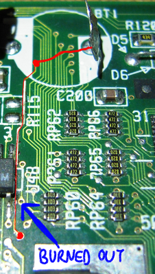
Follow the red line, there's a burned out spot right next to the U48. You can run a wire from the battery terminal to the via in bottom.

T-04YBSC, a new YMF71x based sound card & Official VOGONS thread about it
Newly made 4MB 60ns 30pin SIMMs ~
mida sa loed ? nagunii aru ei saa 😜

Reply 18 of 22, by bjwil1991

User metadata
Rank l33t
Rank
l33t

That's one easy way to do it. If I had to repair a trace using wiring, which gauge wiring should I use? Is it the bigger, the thinner the wiring is? I'm planning on doing something like that on my sound card that needs repairs (although, the current wiring is OK-ish, but, doesn't do the job very well or it's breaking off easily.

Discord: https://discord.gg/U5dJw7x
Systems from the Compaq Portable 1 to Ryzen 9 5950X
Twitch: https://twitch.tv/retropcuser

Reply 19 of 22, by obcbeatle

User metadata
Rank Newbie
Rank
Newbie

Thanks Tiido ... so literally run a wire from the negative battery terminal to your red dot? Sorry ... I may be over my head with this project 😀 Some of the jumper wires I've seen are soldered to the underside of the motherboard. But locating traces from one side of the board to the other I find daunting. The traces are so small plus the traces on each side of the PCB don't always match. Which is probably by design. I think I need to take a class in PCB basics 😀 I've been reading about PCB's and jumper wire repairs today. Does the wire gauge matter much in this case? Thank you!