feipoa wrote:I have an Asus PCI/I-P54SP4 Rev. 1.5 socket 5 motherboard. On the bottom of the motherboard, there appears to be two resistor p […]
Show full quote
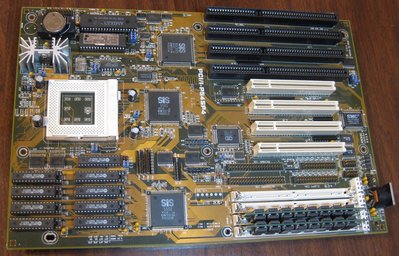
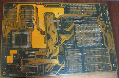
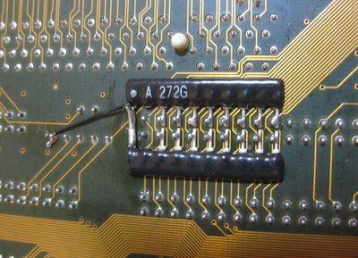
I have an Asus PCI/I-P54SP4 Rev. 1.5 socket 5 motherboard. On the bottom of the motherboard, there appears to be two resistor packs soldered to the pins of the primary IDE connector. It looks like some kind of after thought, either by the end-user or the factory. Does anyone else have a motherboard with this resistor network soldered on? And do you know what its purpose is?
PCI_P54SP4_top.jpg
PCI_P54SP4_bottom.jpg
PCI_P54SP4_resistor_pack.jpg
Can't help you feipoa but it definitely looks like an end-user modification judging from the way the legs on the resistor packs have been cut (too long) and the way the single wire is connected to the other pack without any protective tape. Still a clean job though.
I wonder if they were attempting to attenuate the signal on the data lines, or conversely, raise the TTL low-state voltage to whatever that black wire leads to if that makes any sense.
What is that black wire connected to? is it a ground?