VOGONS


First post, by foil_fresh

User metadata
Rank Member
Rank
Member

Hi yall!

Sorry if this isn't the correct place to make this thread but here goes...

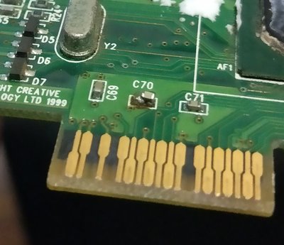
I have recently picked up a Creative TNT2 Ultra to put into my PIII pc but have noticed that a capacitor looks loose/is destroyed.

I've attached the picture of the capacitor (C70) on the board.

Does it look broken or does it look previously repaired? BTW don't worry about the white stuff - it's silicone from a previous HSF mounting operation.

Secondly, how would one identify what it is specifically, and where would one get a replacement capacitor? I have looked at buyICnow.com quickly but realise now I don't know what I'm actually looking for as I don't know the specs.

Help? Lol. Thanks.

Attachments

  • TNT2 Ultra C70.jpg
    Filename
    TNT2 Ultra C70.jpg
    File size
    804.39 KiB
    Views
    732 views
    File license
    Fair use/fair dealing exception

Reply 1 of 9, by Nprod

User metadata
Rank Newbie
Rank
Newbie

- The brown stuff is either corrosion or flux residue
- Even if there was a repair attempt, it doesn't look good and is best replaced properly
- It's likely the same value as C71 and C69 - you can take it off the board an measure it, then look for one with the same capacitance.
- You can often salvage these from useless boards with a hot air gun.
- A schematic would confirm the value 100% but it's unlikely you'll find one online

Reply 2 of 9, by wiretap

User metadata
Rank Oldbie
Rank
Oldbie

Looks previously repaired (poorly) to me, with a glob of solder & flux on the left that got dust all stuck to it. I can tell, because it is sitting crooked, not mounted flush. You can find a donor board of the same model for a replacement, or measure surrounding capacitors of the same size. Or remove the one that's on there and measure it to see if it is good or not. If you need instruction on how to do this, see the link in my signature. Tweezers and a hot air gun will work, but a soldering iron works just as easily and will minimize the amount of the heat put onto the board.

For the physical size of the capacitor, it looks to be a SMD 0603, but you can measure it to be sure. Then you can order a roll of replacements off Digikey, Newark, Mouser. (if you wanted to go with a brand new one)

My Github
Circuit Board Repair Manuals

Reply 3 of 9, by Ozzuneoj

User metadata
Rank l33t
Rank
l33t

I'm not an expert by any stretch of the imagination but it looks like one side of that cap goes to ground, so it may just be a filter capacitor. It may work fine without it. I'd recommend waiting to hear from someone else who actually knows more about this stuff though, just in case. 😀

Now for some blitting from the back buffer.

Reply 4 of 9, by gdjacobs

User metadata
Rank l33t++
Rank
l33t++

MLCC caps are known to fail short from time to time. What does it measure with an ohmmeter?

All hail the Great Capacitor Brand Finder

Reply 5 of 9, by foil_fresh

User metadata
Rank Member
Rank
Member

Thanks all for the replies. Good advice all round.

I've bit the bullet, purchased a soldering kit on ebay and plan to do a resolder on it because it appears to still be completely intact (the cap). I haven't measured anything about the capacitor as i don't have a multimeter.

I plan to flux the area, heat it up with an air gun to remove the cap. I'm going to wick away the leftover solder on the board and then resolder it on, hoping for the best.

If it's still dead I'll have a nice trophy.

This will be my first time soldering, i'm open to any advice. Does it seem like i'm on the right path?

Cheers guys.

Reply 6 of 9, by red_avatar

User metadata
Rank Oldbie
Rank
Oldbie

I really need to learn how to solder as well. With repairing some of my old stuff, I always hit a wall when the next likely fix is resoldering certain components. I got soldering gear but never found something to practice on. There should be like a soldering kit you can buy to test several types of chips and soldering on, so you don't ruin anything important 🤣

Retro game fanatic.
IBM PS1 386SX25 - 4MB
IBM Aptiva 486SX33 - 8MB - 2GB CF - SB16
IBM PC350 P233MMX - 64MB - 32GB SSD - AWE64 - Voodoo2
PIII600 - 320MB - 480GB SSD - SB Live! - GF4 Ti 4200
i5-2500k - 3GB - SB Audigy 2 - HD 4870

Reply 8 of 9, by red_avatar

User metadata
Rank Oldbie
Rank
Oldbie
Nprod wrote:
foil_fresh wrote:

This will be my first time soldering, i'm open to any advice.

Don't start fixing the board right away, first practice a bit on a scrap board that you don't care about.

Yeah that's what I meant - but then you still don't know if what you did worked 😉. Or maybe a really cheap board you don't intend to use - unsolder and resolder some stuff and see if it still works.

Retro game fanatic.
IBM PS1 386SX25 - 4MB
IBM Aptiva 486SX33 - 8MB - 2GB CF - SB16
IBM PC350 P233MMX - 64MB - 32GB SSD - AWE64 - Voodoo2
PIII600 - 320MB - 480GB SSD - SB Live! - GF4 Ti 4200
i5-2500k - 3GB - SB Audigy 2 - HD 4870

Reply 9 of 9, by dkarguth

User metadata
Rank Member
Rank
Member

I wouldn't start off with smd stuff if I were you, I would practice on some through hole stuff first. Also, pay attention to what kind of solder you're using. Based upon the era of the card, I'd say that it used non - lead solder, which is trickier than leaded solder.

"And remember, this fix is only temporary, unless it works." -Red Green