VOGONS


First post, by GabrielKnight123

User metadata
Rank Oldbie
Rank
Oldbie

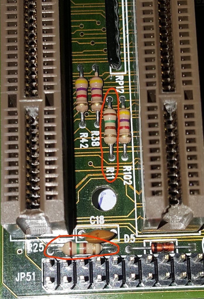
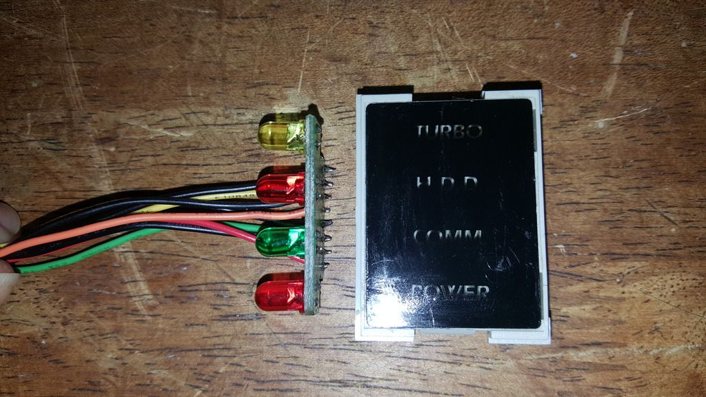
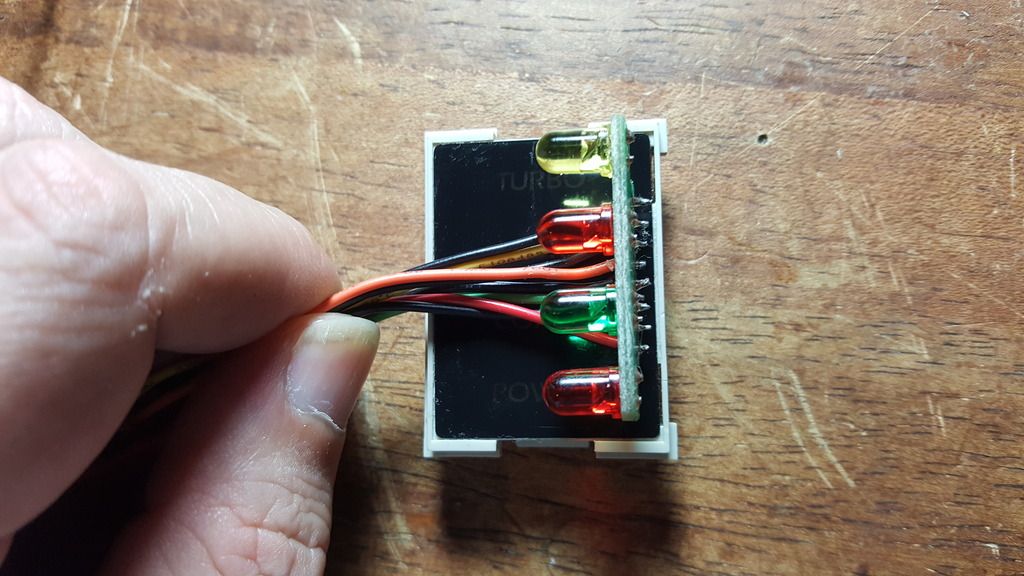
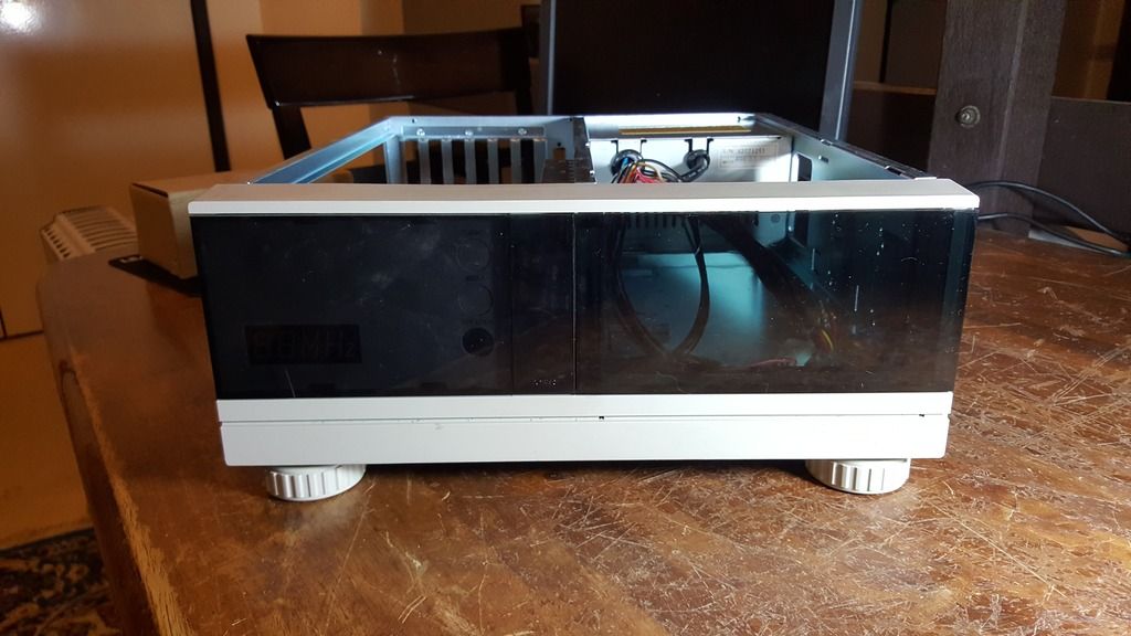
I have a new old stock AT case thats never been used till now, I installed and built a 486 out of it but then I noticed all the LED's for the lights of the "Power/Turbo etc." at the front of the case are very, very dim, I checked the output of the LED headers on the motherboard and they output at 5 volts, im not sure if this is enough or not but the LED's (for the case) only show light down the barrels of the LED's and not outwards so you have to look down on the LED to see its light but im guessing when the LED bank is in its housing its meant to bounce the light back to fill the words "Power/Turbo/HDD/Comm" but in this situation this is not working either. I would like to replace the LED's but don't LED's need a resistor or something to stop it from blowing up? I also know there are different types of LED's that either show light only in one direction like my ones do (down the barrel) or ones that show light in all directions, Here are some pictures to help show what I have, what type of LED would be best but something that wont over brighten so as to not make the other words in the housing light up unnecessarily.

20190131_034550_zps1mdjdo0j.jpg

20190131_034511_zpscrx5k9qw.jpg

20190131_034652_zpslqxmip1o.jpg

20190131_034722_zpsjgrrvazz.jpg

20190131_034817_zpswrr4ahcg.jpg

02_zpsdyck56wr.jpg

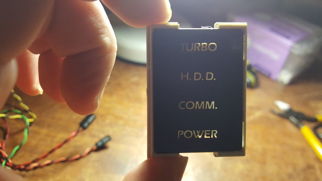
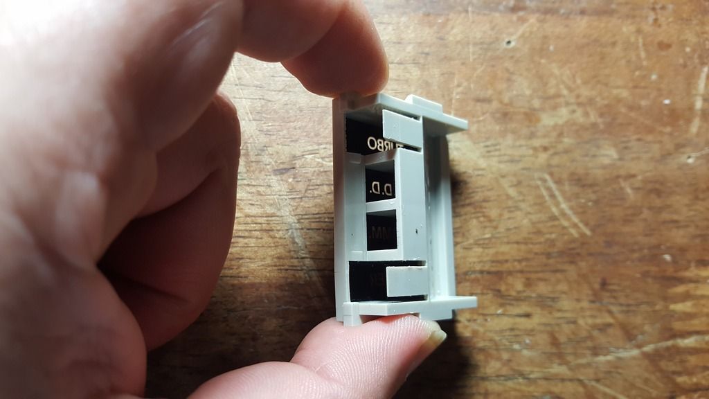
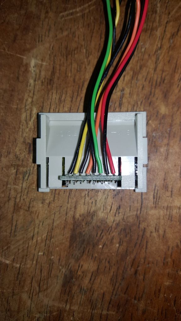
Edit: the housing for the LED's has individual channels to stop the light from one LED going into its neighbouring LED.

Reply 1 of 12, by dkarguth

User metadata
Rank Member
Rank
Member

Your motherboard *should* already have a current limiting resistor for each LED. All of my motherboards do, but I don't want to make a universal statement. My first step would be to test the LEDs by themselves. A safe current for LEDs of around that size is 15-20 miliampres, so with a voltage drop of about 2v, you should need around a 220 ohm resistor when connecting it to straight 5v. If you have a 5v supply, you should connect the LEDs to it across the resistor to see if they are any brighter. Maybe there's something going on with the motherboard?

"And remember, this fix is only temporary, unless it works." -Red Green

Reply 2 of 12, by GabrielKnight123

User metadata
Rank Oldbie
Rank
Oldbie

Thanks dkarguth ive been using a 5.06 volt power supply to test the LED's one by one but they are very dim still and if I use the power supply on another case the LED's are bright so im guessing something is wrong with them, I didnt blow out any LED's when testing them without a resistor from the power supply but I didnt run them for long they did get a bit hot though. Ive had this motherboard in another case and the LED's were just fine so the mobo probably has current limiting resistors built in I just need to pop in some 5 volt LED's or should I get another type?

Reply 3 of 12, by dkarguth

User metadata
Rank Member
Rank
Member

Those leds are most likely the common 5mm type. If you have a soldering iron, you should be able to just replace those leds with some newer ones. It is possible that they have just grown dim with age. Just make sure to hook the led up in the correct polarity, though, or they will not work at all.

"And remember, this fix is only temporary, unless it works." -Red Green

Reply 5 of 12, by SirNickity

User metadata
Rank Oldbie
Rank
Oldbie

I have never met a motherboard (or I/O card) header meant to drive an LED that wasn't current-limited. LEDs are not voltage sinks, they are current sinks. Like any diode, they require a certain forward voltage (1 to 3 volts or so) to overcome the junction-whatsit, and after that, they're essentially a short circuit. So, you can (in theory) fry a red LED with a measly 2.5V source as long as it can dump enough current at that voltage. The only thing that saves you w/o a current-limit is various impedances -- in the LED, in the cabling, in the PSU... That's why a coin cell is typically safe. It can't produce 100mA at 3V.

Most headers will only drive an LED at a few mA. 20mA is pretty hot, and right at the limit of acceptable use for a normal indicator LED. You can see them clearly at as low as 1mA, and usually at near-enough "full" brightness by 5-10mA.

You might measure 5V across the header, but only at near-zero load. If you place a 470 ohm resistor across that, you'll notice the voltage drop -- and more with lower value R. It will survive a dead short, but it's not ideal. (You may overheat the current-limiting resistor on the motherboard after a while.)

Those LEDs do indeed look like garden-variety 5mm indicators. You can get replacements anywhere. Beam angle and mcd (brightness) specs are usually listed from the better parts distributors, and can help classify equivalent parts in different colors. Beware, though, that 1000mcd red is not the same perceived brightness as 1000mcd blue or green. IIRC, red is most bright, then yellow, green, blue. I don't recall exactly the scale -- maybe 1:2 between red and green, and 2:3 on green to blue?

A trick that I use for polarity -- that is not an absolute guarantee, but has yet to lead me astray -- is to look inside the lens at the two poles. They are not split down the center, but one should be noticeably larger. The smaller is usually the negative side. Verify with a meter in continuity mode (it will probably barely light up, but should be visible.)

Reply 7 of 12, by dkarguth

User metadata
Rank Member
Rank
Member
SirNickity wrote:

I have never met a motherboard (or I/O card) header meant to drive an LED that wasn't current-limited.

I actually used to have a very odd motherboard out of a pre-built generic computer from the 286 era that actually had resistors on the led cables. I traced the power LED header out of curiosity, and it was connected straight to the 5v line of the power supply without any resistors! Weirdest thing I've ever seen. Got rid of it a long time ago because its cmos battery leaked and corroded it beyond repair. Too bad I don't still have it, or I would post a picture of it.

"And remember, this fix is only temporary, unless it works." -Red Green

Reply 8 of 12, by GabrielKnight123

User metadata
Rank Oldbie
Rank
Oldbie

Thanks everyone you've been a great help, SirNickity so if I go for a 5mm (I measured them to be as 5mm) I should be set if I use 5-10mA? I dont know much about electronics but I traced the two headers for the LED's for the power and turbo LED and they both have a resistor and if im right they are 150 ohms 5% here is a pic:

Resistors_zpsc7mbamyh.jpg

Is it possible to find out the current output for these LED's on the motherboard with a multi meter so I can know what milliamp LED to buy? I have a multi meter but again im not really knowledgeable in this field. Sorry Merovign there is no brand or naming on the whole case but I posted more pictures in this thread: New Old Stock PC Case Ready For New Build

Reply 9 of 12, by dkarguth

User metadata
Rank Member
Rank
Member

Since your motherboard has current limiting resistors, you don't need any additional resistors. You should be fine with any standard 5mm led you decide to put on there. Just find one that shines the right brightness for your preference and then install! I would buy one of those assortments off of ebay/amazon if I were you, it gives you a nice selection and they are normally pretty cheap, too.

Also, modern LEDs put out a lot more light for the amount of current that is applied to them, so if you decide that a 5mm LED is too bright for your taste, it wouldn't hurt anything to put a 3mm LED in there instead. Just make sure you get the polarity right: the long lead on the new led is the positive.
I think you could safely assume that the black wires go to ground, but here's another method if you want to double check anyway. The easiest way to find the polarity of the old LED would be to look for a flat side if they have one. The skirt around the base of the bulb that sits against the board often has a flat side on it. That side is the negative. Better to check twice and only solder once!

Here's a link to a generic ebay LED kit. There are cheaper ones than this that have less LEDs if you don't think you'll ever need any LEDs again.
https://www.ebay.com/itm/150pcs-3mm-5mm-LED-L … 4781e%7Ciid%3A1

Also, just curious, what exactly does the "COMM" light do? Does it show activity on the serial ports? I've never seen one of those before on a PC case.

"And remember, this fix is only temporary, unless it works." -Red Green

Reply 10 of 12, by GabrielKnight123

User metadata
Rank Oldbie
Rank
Oldbie

You know what im not really sure I was going to ask here on Vogons about the COMM LED, the plug end is the same as a normal 2x LED plug end eg. turbo LED or HDD LED and has a "COMM" sticker on the cable plug but nothing else, is there some way to plug it into a CD/DVD drive to see when it has activity like a HDD?

That ebay link for the LED kit shows:
For red ,yellow ,green , 3mm 5mm, it is 2V , 20mA ,forward voltage is 2-2.2V.
For blue , white, , 3mm,5mm, it is 3V , 20mA, forward voltage is 3-3.2V.
but none of them are 5 volts would it be wise/ok to use them on the header that outputs 5 volts?

Reply 11 of 12, by SirNickity

User metadata
Rank Oldbie
Rank
Oldbie

LEDs are not voltage devices. The voltage spec is the forward voltage drop across the diode. It's the way diodes work. They (essentially) don't conduct until the voltage potential across them reaches that fwd voltage, then they turn into a short circuit. So, for the red one, in theory, 1.75V would produce no light, and would pass no current. 2.5V would potentially drive it to death if the PSU was able to produce enough current through the complete circuit. The resistor imposes a mandatory limit to the amount of current that can flow through the circuit.

You can determine a resistor's ideal value with a formula:

R = (Vsup - Vfwd) / I

...where R is the resistor value in ohms, Vsup is the supply voltage (5V), Vfwd is the LED's forward voltage (say 2.2V), and I is the desired current, in amps (so, 0.005 = 5mA). For 5mA, you would need a 560 ohm resistor. Change any of the values (supply voltage, fwd voltage drop, desired current) and the R will change. (But in practice, you would settle for a middle-of-the-road value and call it good for any color. Maybe tweak for high fwd-voltage LEDs like blue or white.)

If the motherboard is using a 150R resistor, and you use a red LED, it will be driven at 18mA. I = (Vs - Vf) / R

That's a lot of current. It's not TOO much, if the LED claims it can be driven at 20mA, but I do imagine it would reduce the lifetime of the LED. That may be why yours are starting to fail -- although LED reliability has come a long way, as has efficacy. If you want a less eye-searing display, you could either: 1) add another series resistor in-line; 2) replace the resistor on the motherboard with a higher value; or 3) use a relatively inefficient LED and keep driving it hard. OTOH, maybe behind the filter lens, you need 18mA. LED's are cheap and easy to replace, and it should last a while at least, even running full tilt.

Reply 12 of 12, by SirNickity

User metadata
Rank Oldbie
Rank
Oldbie
dkarguth wrote:

I actually used to have a very odd motherboard out of a pre-built generic computer from the 286 era that actually had resistors on the led cables. I traced the power LED header out of curiosity, and it was connected straight to the 5v line of the power supply without any resistors! Weirdest thing I've ever seen.

Ha, yeah.. I had no doubt that at least one existed out there somewhere. I've just never seen one. It's definitely common practice to limit current on the board, but there's always going to be that one engineer that marches to the beat of his/her own drum.