VOGONS


First post, by algernon

User metadata
Rank Newbie
Rank
Newbie

Hi to all sirs,

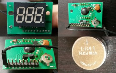
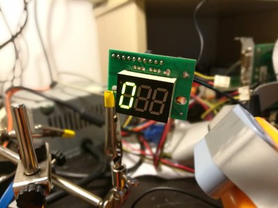
i need help to configure this Mhz Display..i don't know how to connect it to the MOBO..a isa-only 486DX33.
NO documentation found on the internet.
there is a model number on it: D900 SC and one wire connected to anything...

thanks for your help!

Danilo from Italy.

Attachments

  • 486.jpg
    Filename
    486.jpg
    File size
    329.46 KiB
    Views
    559 views
    File comment
    different view of the MHZ display
    File license
    Fair use/fair dealing exception

Reply 1 of 6, by GabrielKnight123

User metadata
Rank Oldbie
Rank
Oldbie

This is the first time ive seen one like yours as all the ones Ive had needed jumpers to set the digits on the display so im guessing the + and - are to change the digits one at a time somehow as apposed to DC volts and the on board battery is to keep the settings when programmed. Usually your motherboard has a 3 pin turbo switch header for the turbo switch on the front of your pc case and then a turbo led will go from your pc case to your 3 digit display but then you will need power to run the 3 digits in a form of a molex bridge to your power supply or some power supply's have this cable for you but sorry I cant help any more than this someone else will probably know more. Was there any other cables with this display other than the single black one connected to "E" (earth?)

Reply 3 of 6, by computerguy08

User metadata
Rank Member
Rank
Member

You can check with a multimeter which of the pins is the ground using the negative pole of the button battery socket. I suspect that + and - are the 5V and GND (respectively), which should be connected to the power supply (don't take this information for granted, I've made an assumption).

Check this page: http://www.minuszerodegrees.net/led_speed_dis … 0-%20DP-524.jpg. There may be a GND pin for the turbo led as well.
While the one showed here uses jumpers, there should be the same kind of connections at the back, regardless of your display's internal circuit, in order to be compatible with any motherboard.

Reply 5 of 6, by algernon

User metadata
Rank Newbie
Rank
Newbie

done! At least it works.
Plus=5v Minus=GND

Now i have to understand how to change numbers..

Thanks for the support!

Attachments

Reply 6 of 6, by dkarguth

User metadata
Rank Member
Rank
Member

What an unusual display module. I've never seen one quite like that before.

"And remember, this fix is only temporary, unless it works." -Red Green