VOGONS


First post, by treeman

User metadata
Rank Oldbie
Rank
Oldbie

to make it short I got myself a badly battery corroded 486 board with a 100mhz cpu as a new project the dirtier the better. Spent last few days fixing broken tracks soldering a few things that got in the way etc.

It finally powered on but was short lived got. about 6 boots and not posting.

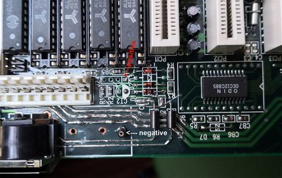
I checked cpu both chipsets and they are warm, the voltage regulator however is hot, hot to the level it is nearly burning but not that hot that have to take finger off.

I measured both sides with a multimeter one side is 1.5V another is .08~.09V.

I never have dealt with regulators so I have no idea what expected behaviour is.
Anybody can help out?

Last edited by treeman on 2019-03-01, 22:28. Edited 1 time in total.

Reply 2 of 40, by treeman

User metadata
Rank Oldbie
Rank
Oldbie

without cpu I got 1.6v and 1v
I changed mode to 5v measured regulator and shows 0 on both ends so that is good, but still no post, looks like there is multiple problems still. But this is a good idea to start looking between cpu and regulator maybye 1 problem leads to another

If I have the cpu set on 3.3V what reading should I be getting on healthy system? 5v and 3.3~3.5?
thanx

Reply 3 of 40, by rasz_pl

User metadata
Rank l33t
Rank
l33t

so 5V is sagging down to 1.6 and AT supply doesnt trigger protection? afaik they had some kind of undervoltage limits
have you tried another psu?

Open Source AT&T Globalyst/NCR/FIC 486-GAC-2 proprietary Cache Module reproduction

Reply 4 of 40, by treeman

User metadata
Rank Oldbie
Rank
Oldbie

I tried a different psu and still same got 1.56V and .9V close enough.

I tested some of the electrolytic capacitors there is about 20 small 22uf 25V some of them held .03V charge but some hold 0, since this is a project I think ill change them all

Reply 6 of 40, by treeman

User metadata
Rank Oldbie
Rank
Oldbie

unfortunately this board doesn't have any through hole tantalum capacitors and the smd ones.... well you know how many there is and I don't think any way to test without desoldering

Reply 7 of 40, by rasz_pl

User metadata
Rank l33t
Rank
l33t

measure 5V AT supply rail, does it sag too? search for whats between AT power connector and voltage regulator
post picture of the board for good measure

Open Source AT&T Globalyst/NCR/FIC 486-GAC-2 proprietary Cache Module reproduction

Reply 8 of 40, by treeman

User metadata
Rank Oldbie
Rank
Oldbie

So I measured voltages on the rails under the power plug going from pin 1
5, 5, 12, 11.3, G, G, G, G, 4.8,5,5,5

(I left out negative voltages to make it simple)

I measured the 3 rails that I repaired they are 11.3 12 and 5 same as direct from power plug.

the 11.3V seems too low? I did have to remove the power plug in order to fix the tracks I may have to look into the pin and resolder/clean the one doing 11.3V

anyway this is the board before repair, original picture from the seller I should of taken a better myself but I never planned to document it

s-l1600.jpg
Original condition

IMG-20190225-151152.jpg
After repair of spilled battery whole picture, set up for 5v operation with 5v cpu to bypass voltage regulator

IMG-20190225-151201.jpg

IMG-20190225-151211.jpg

IMG-20190225-151143.jpg

I think the solder joins for power plug and keyboard are good, I had to remove both. Some of the pins on the power plug were dark, I think it was just dirt not corrosion so I cleaned them with sand paper. I may have to desolder and clean the 11.3V one, unless this variation is ok, I think 11.3V from whats supposed to be 12V is too much drop

Oh yeah I tested the 3 main power rail traces that I tinned and jumped, they measure fine at the end of the last isa slot

The two keyboard traces both measure 5V

I checked all the traces for continuity when I did it first but I should of also checked for voltage

Reply 9 of 40, by treeman

User metadata
Rank Oldbie
Rank
Oldbie

ha ha looking at my own pcitures I see a few spots where there is some small corrosion still, funny how it always comes out more in photos

Reply 10 of 40, by TheMobRules

User metadata
Rank Oldbie
Rank
Oldbie

The 11.3V in pin #4 is actually the -12V line, so I assume it's -11.3V. In that case you shouldn't worry about it, in many cases it's a bit off when there is no load on that line, and -12V is only used for the serial ports IIRC, so that shouldn't be the cause of your issues (also, the 4.8V in pin 9 is actually the -5V line).

It's not clear from your other posts, but have you confirmed that the regulator is getting 5V on its input pin? I can't see clearly the part number of the regulator on your pictures, maybe if you get a better shot of it I can suggest some other tests you can do?

Reply 11 of 40, by treeman

User metadata
Rank Oldbie
Rank
Oldbie

indeed both those pins are negative, thanx for letting me know saved me from wasting time on those

IMG-20190225-173052.jpg
IMG-20190225-173101.jpg
IMG-20190225-173140.jpg

and this is the regulator, current I set it to 5v so its not being used but when set on 3V I put ground on middle pin then put positive on right then on left one side gives me ~1V other side gives me ~1.5V
IMG-20190225-173547.jpg

I think im back to square 0 going to clean and inspect all the small traces in the affected area

It is still not booting with 5V but the cpu does get hot

Reply 12 of 40, by Deunan

User metadata
Rank Oldbie
Rank
Oldbie

TIP127A is a PNP power darlington, not your typical linear regulator like for example LM317.

Anyway, looking at the photo, from left to right the pins of that transistor should be connected like this: Vreg, output (to 486 socket), +5V
That 5V might be connected permanently or through a jumper so check that. If you can't measure 5V there (including when the regulator is bypassed, in case it's not jumpered) but something much lower then I'm afraid that TIP127A is shorted internally and has to be replaced.

Vreg should be set to about 1V lower than what you would get on the output, this is done via the jumpers. Either by connecting a resistor divider direcly to that pin, or there might be an op-amp somewhere nearby but since this is a darlington setup just the resistors would do. If you can, desolder the TIP and then check the voltages again.

Reply 13 of 40, by quicknick

User metadata
Rank Oldbie
Rank
Oldbie

Some time ago I repaired a similar board. It was a bit less damaged than yours, and I haven't documented everything so my memories could be somewhat sketchy, but I remember that I couldn't get the board to boot after the repair no matter what. I think it got stuck with a 07 error on the POST diag card. Tried with a 3xAAA rechargeable pack connected directly where the leaky battery was, tried with 2, 3 and 4xAAA alkalines at the ext. battery header, no luck. In the end, this is what worked for me:

ATC1415new.jpg
Filename
ATC1415new.jpg
File size
624.71 KiB
Views
1100 views
File license
Fair use/fair dealing exception

A CR2032 holder, connected with the negative side at the original battery's negative, and the positive at the external battery header pin 1 (with the actual header removed). I actually used two break-away machine pin headers for connecting the CR2032 holder, and the one on the positive side... well, broke away when I removed the holder to take the picture 😁 . I'll solder a new one later on. Good luck!

Edit: cannot help you with VRM measurements since my board is equipped with a 5-pin MIC29152BT regulator, but if the VRM is defective on yours, it should at least start with 5V CPUs.

Reply 14 of 40, by treeman

User metadata
Rank Oldbie
Rank
Oldbie

I removed the regulator and when cpu is set for 3.3V mode one of the pins is showing 5V and the other 1.5V so looks like the regulator might be faulty. Still no post on 5V mode and no regulator. So still some problem here, I tried a external battery connected to the external battery pins and the negative connected to the origanal battery negative pin like suggested but still no go.

cpu does get hot and I am getting beeps if remove the ram so its not fully dead. Anyway looks like got the regulator problem solved and going to enjoy the further challenge of diagnosing the next issue. thanx guys

Reply 15 of 40, by Deunan

User metadata
Rank Oldbie
Rank
Oldbie

You can replace that TIP127A with a 125 or 126 as well, so long as it's not a *TU version. These are only ~2W rated and will blow pretty much instantly. I'd suggest adding a bent piece of aluminum or copper plate to form a simple radiator - this transistor didn't have it and as you can see didn't survive.
Also, get a cheap test card (ISA+PCI combo preferably). Beeps alone will not tell you a lot and the card is much better tool to figure out what is going on.

Reply 16 of 40, by treeman

User metadata
Rank Oldbie
Rank
Oldbie

So I got the board to wake up, kind of got me thinking what quicknick said about the external battery connector which is also to clear bios pin in 3-4 combination. Weird the board posts eveytime with the jumper on clear cmos 3-4 combo, so I tried a external coin on pin 1-4 which means have to take off 3-4 and the board goes dead.

It will only boot with clear cmos jumper, weird. Also does not detect keyboard but the 3 lights flash on boot and keyboard did work the very first time I had the board booting.

So got a check list from here.

1 solder voltage regulator back in and check directly on cpu socket
2 go over the 2 keyboard traces again
3 remove the bios chip and save the image with external bios reader/Writer see if any corruption
4 Inspect keyboard controller

IMG-20190228-113744.jpg

Reply 18 of 40, by treeman

User metadata
Rank Oldbie
Rank
Oldbie

yes but those pins are clear and traces look clean, I suspect something is telling the bios lock is on, keyboard controller, but I don't see one the odin chip near the bios must handle that?

and possibly the capacitors / resistors around keyboard plug, this items are all in the area where battery spilled I am hoping something there is shorting and telling bios the lock is on

Reply 19 of 40, by quicknick

User metadata
Rank Oldbie
Rank
Oldbie

Well, this board has some weirdness about that RTC area, and in a way I'm glad the coin cell mod that I improvised is now broken because I wasn't very happy about how it turned out. Also, I now realised that having the CR2032 connected between the original GND and pin 1 of the ext. bat. header should be exactly the same as connecting it between pins 4 and 1, yet in this instance it didn't work. So I'll have to investigate further, but unfortunately I don't have much spare time these days.

There's also this. It's in Russian, so I google-translated it, but it certainly refers to the same board getting stuck with the same code 07. Do you have a POST diag card, I'm really curious if yours also hangs on 07 when it isn't booting...