VOGONS


First post, by feipoa

User metadata
Rank l33t++
Rank
l33t++

I noticed today that a segment of the LCD MHz display stopped lighting up. Is this fixable, or do I need to find a new display? Thanks.

Fix_LCD_MHz_Display.jpg
Filename
Fix_LCD_MHz_Display.jpg
File size
64.7 KiB
Views
612 views
File license
Fair use/fair dealing exception

Plan your life wisely, you'll be dead before you know it.

Reply 1 of 15, by Tiido

User metadata
Rank l33t
Rank
l33t

If wiggling jumpers isn't helping then it is quite likely the display needs replacement. Luckily they have standard pinouts and it isn't difficult to find a replacement.

T-04YBSC, a new YMF71x based sound card & Official VOGONS thread about it
Newly made 4MB 60ns 30pin SIMMs ~
mida sa loed ? nagunii aru ei saa 😜

Reply 2 of 15, by feipoa

User metadata
Rank l33t++
Rank
l33t++

That is a good point -the jumper may have corrosion or may not be tight any more. Let me give that a go. I did notice that flicking the case really hard with my finger brought a dim light back to the faulty segment.

Plan your life wisely, you'll be dead before you know it.

Reply 3 of 15, by wiretap

User metadata
Rank Oldbie
Rank
Oldbie

I had one that I received burned out. (2 or 3 non-lighting segments, 3 dim ones) First I tried reflowing the solder joints, then cleaning all the jumper pins.. didn't solve it. I just ordered a new 7-segment display for it for $3 and that solved it. I'm guessing the prior owner connected voltage directly to the segment jumper pins by mistake, or it was just old and died.

My Github
Circuit Board Repair Manuals

Reply 4 of 15, by Tiido

User metadata
Rank l33t
Rank
l33t

It is possible to burn out segments by lighting up only one or two of them (while setting up the numbers). There's usually only *single* current limit resistor for all the segments and it functions right only if there's many segments lit, with just one or two the lit segments will have huge current through them and are easily damaged.

T-04YBSC, a new YMF71x based sound card & Official VOGONS thread about it
Newly made 4MB 60ns 30pin SIMMs ~
mida sa loed ? nagunii aru ei saa 😜

Reply 5 of 15, by SirNickity

User metadata
Rank Oldbie
Rank
Oldbie

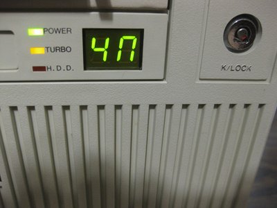
Did these things ever happen to establish a common footprint for the display PCB? That is, the mounting hole(s), size and position of the board relative to the window, etc.. My Pentium case uses a harder-to-find 3-digit display that fits in the same area as the common 2-digit displays. It's definitely different than the 2-digit display PCBs that I have, but all three of those seem to be somewhat interchangeable. (Although they are probably from the same manufacturer -- the original cases are similar as well.)

The reason I ask is that I've already laid out a new PCB for the 3-digit display. The original board's controller IC didn't work, and I couldn't figure out the single-letter legend over all the control pins anyway, but the LED module itself was fine. On my board, I used two 10-bit DIP switches to set turbo and non-turbo speeds, and an ATmega164PA to read the inputs and multiplex the display -- with current limiting per-segment. This could be adapted to a 2-digit controller easily enough, and I could make the files available for anyone who wants to spin their own. No idea how many people have the appetite for dealing with SMD parts and flashing microcontrollers, but IMO setting the display in binary is a lot easier than dealing with the weird common / turbo / non-turbo jumper arrangements they tend to use.

Reply 6 of 15, by feipoa

User metadata
Rank l33t++
Rank
l33t++

I see two fairly standard sizes for the display box, the larger and smaller boxes. Both come in 2-segment and 2-sgement+1. I haven't checked the the PCB mounting leads though.

Anyway, moving on and off the jumpers didn't have any effect on my display. I had to flick it several times in harder and harder consecutive flicks to get that particular segment of the LCD to light up. If I then flick it one too many times, the light goes out again. So I have to start flicking it again with my finger. The first flick gets the light to just come on, the next flick, its a little brighter, and so forth, but the best I can get it to illuminate is at about 80% intensity - one more flick and the light goes out again. Anyone know what this means from a physical stand-point?

Plan your life wisely, you'll be dead before you know it.

Reply 7 of 15, by SirNickity

User metadata
Rank Oldbie
Rank
Oldbie

Sounds like a bad solder joint to me. You might have to do more localized flicking to find out.

I guess the LED could have failed, structurally. I've never heard of that happening though. AFAIK they're entirely encapsulated so the bond wires wouldn't have much room to move.

Reply 8 of 15, by treeman

User metadata
Rank Oldbie
Rank
Oldbie

does that segment fail in both states? HI and LOW?
I have a display where it will only light up in 1 state but not the other, seeing if the segment behaves the same in both states could help you rule out a few things

Reply 9 of 15, by feipoa

User metadata
Rank l33t++
Rank
l33t++

Yes, both states it fails. Does that point to a solder joint or the display itself? Are these LED's or LCD's? I always assumed they were liquid crystal, but some of you are calling the LED, so now I'm confused.

Plan your life wisely, you'll be dead before you know it.

Reply 10 of 15, by treeman

User metadata
Rank Oldbie
Rank
Oldbie

It won't hurt to melt some fresh solder onto the join and mix it, pretty quick way to rule out a cold/cracked joint, while your at it checkout the whole pcb under a magnifying glass

Reply 11 of 15, by feipoa

User metadata
Rank l33t++
Rank
l33t++

I'd have to pull out my SCSI2SD, my CF, and floppy drive to access the display, also I'd need to remove all the jumper wires. It is working at 80% brightness now and is hardly noticeable, so I think I won't take further action until it goes out again. I'm pretty burned out with moving around the SCSI2SD, CF, and floppy. The mounting is rather unconventional.

Plan your life wisely, you'll be dead before you know it.

Reply 12 of 15, by treeman

User metadata
Rank Oldbie
Rank
Oldbie

yeah those are pretty annoying to take out the display In have that won't show a low state I left like is too much trouble, but one of my other displays actually comes our forwards so can extend it out without removing anything behind it, I accidentally discovered this but every case is different. I was thinking would be a good cheat if you could flip the display upside down somehow then the burned out segment would be the empty top on top of the 4

Reply 13 of 15, by feipoa

User metadata
Rank l33t++
Rank
l33t++

I thought of that as well, but some digit will still be affected in one of the states. Low is 20 and high is 40. In the future, it will be Low is 33 and High is 66. But I need to figure out how to retain a removable heatsink to the QFP version of the SXL2-66.

Plan your life wisely, you'll be dead before you know it.

Reply 14 of 15, by treeman

User metadata
Rank Oldbie
Rank
Oldbie

was worth a mention, have you tried a different jumper?
Once I was short 1 jumper so made my own by bending a cable and the segment with the homemade jumper always took longer to light up then the rest

Reply 15 of 15, by SirNickity

User metadata
Rank Oldbie
Rank
Oldbie

If it acts the same in either L or H mode, then that would point to the segment joint. Although, since the segment is common to both speeds, if your display is like mine there's a separate jumper position for L Only, H Only, and Common. So it could be the Common jumper that's failing. Although you said you fiddled with the jumpers and it made no difference, so I'm sticking to the segment joint.

They are LED, by the way -- not LCD.