VOGONS


Reply 100 of 139, by HanJammer

User metadata
Rank Oldbie
Rank
Oldbie
Deunan wrote:

F and S are very close in terms of speed but I think F uses less power. In most cases F will work fine as S replacement.
If replacing U58 doesn't cure the mobo, try with the resistors again and check the voltages - I'm curious if the bit 4 will still show different readings. In fact if you get odd voltages still, remove U58 from socket and measure again. There's a '373 connected there that could have a faulty input.

I did a quick test and motherboard won't boot - same behaviour, although it did a nice clear long beep one time instead of this screeching noise.

So what exactly should I check again? With or without resistors in 8288?

With pin4 and pin7 8288 resistors and nothing else U58 voltages are like this (same with F245 and old S245):
#1 0,11
#2 4,74
#3 4,74
#4 4,74
#5 4,74
#6 4,74
#7 4,74
#8 4,74
#9 4,74
#10 0,01
#11 1,80
#12 1,80
#13 1,79
#14 1,79
#15 2,2
#16 1,80
#17 1,80
#18 1,80
#19 0,22
#20 4,74

with U58 removed from it's socket:
#1 0,11
#2 4,74
#3 4,74
#4 4,74
#5 4,74
#6 4,74
#7 4,74
#8 4,74
#9 4,74
#10 0,01
#11 1,74
#12 1,74
#13 1,73
#14 1,73
#15 2,1
#16 1,39
#17 1,39
#18 1,51
#19 0,22
#20 4,74

#U54 373:
#1 3,74
#2 3,55
#3 1,73
#4 1,73
#5 3,58
#6 3,63
#7 1,73
#8 1,73
#9 3,67
#10 0,01
#11 0,08
#12 3,87
#13 1,52
#14 1,52
#15 3,85
#16 3,86
#17 1,52
#18 1,53
#19 3,84
#20 4,74

New items (October/November 2022) -> My Items for Sale
I8v8PGb.jpg

Reply 101 of 139, by Deunan

User metadata
Rank Oldbie
Rank
Oldbie

Hm. Just to confirm, this was tested with no CPU, no 8288 and no BIOS ROM?
There's something wrong still with bit 4. It's weird that you get 2.2V on U58 pin 15, and yet only 1.52V on U54 pin 13. These should be connected so why is it different? Can you double-check the schematic, these should be the same signal:
- U58 pin 15
- U54 pin 13
- ROM socket pin 16

Reply 102 of 139, by HanJammer

User metadata
Rank Oldbie
Rank
Oldbie
Deunan wrote:

Hm. Just to confirm, this was tested with no CPU, no 8288 and no BIOS ROM?

No CPU, no 8288 (just pin 4 and 7 resistors to GND), no BIOS ROM.

Deunan wrote:
There's something wrong still with bit 4. It's weird that you get 2.2V on U58 pin 15, and yet only 1.52V on U54 pin 13. These sh […]
Show full quote

There's something wrong still with bit 4. It's weird that you get 2.2V on U58 pin 15, and yet only 1.52V on U54 pin 13. These should be connected so why is it different? Can you double-check the schematic, these should be the same signal:
- U58 pin 15
- U54 pin 13
- ROM socket pin 16

Just checked and I confirm, these pins are connected. Buzzer beeps.
U58#15 vs U54#13 - 0,11Ohm
U58#15 vs ROM#16 - 0,26Ohm
U54#13 vs ROM#16 - 0,28Ohm

BUT... I observed strange behaviour - when I powered on the board and immediately checked the voltage on these pins was around 3,8V, but it falls rapidly. 2 minutes later and now it's 1,4V.
That explains the differences in voltages (I measured them chip after chip taking notes and it takes time). It has to do with chips getting warm or caps getting charged because when I power down the board and power it up immediately the voltage on these pins raises just a bit. I have to wait way longer for it to be significantly higher again...

New items (October/November 2022) -> My Items for Sale
I8v8PGb.jpg

Reply 103 of 139, by HanJammer

User metadata
Rank Oldbie
Rank
Oldbie

Check this out: https://youtu.be/rE0bbTAkncs
Look how it starts rising, then breaks down and strarts falling...

I observed higher voltages on these pins (upto 3,8V I think) when mobo was cold but it quickly fell down to ~1,4V.

New items (October/November 2022) -> My Items for Sale
I8v8PGb.jpg

Reply 104 of 139, by retardware

User metadata
Rank Oldbie
Rank
Oldbie
HanJammer wrote:

That explains the differences in voltages (I measured them chip after chip taking notes and it takes time). It has to do with chips getting warm or caps getting charged because when I power down the board and power it up immediately the voltage on these pins raises just a bit. I have to wait way longer for it to be significantly higher again...

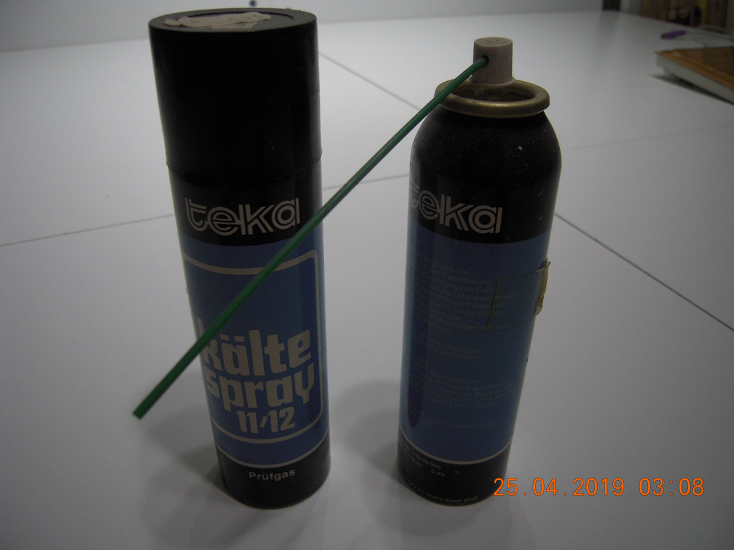
do you have freeze spray?

Reply 106 of 139, by retardware

User metadata
Rank Oldbie
Rank
Oldbie

In case you want to get some, take care the tube (see right can) is included.

DSCN0062.jpg

DSCN0063.jpg

This brand probably no longer exists, as it is genuine freeze spray made in GDR, probably some time beginning to mid 1980s.
Genuine Freon 😵
It costs very little and can save a lot of time finding which component fails when it is warm.

Reply 107 of 139, by Deunan

User metadata
Rank Oldbie
Rank
Oldbie
HanJammer wrote:

Check this out: https://youtu.be/rE0bbTAkncs
Look how it starts rising, then breaks down and strarts falling...

I observed higher voltages on these pins (upto 3,8V I think) when mobo was cold but it quickly fell down to ~1,4V.

Hm. Still, why would that one be special - can you test if any other 2, picked at random, data bits also have this voltage drop after power on? Or is it just bit 4?

This data bus should also be connected directly to the 8237A DMA chip. It's socketed so remove it and test again if you get this behaviour. Especially whether or not it's only on bit 4.
In fact you can try booting the mobo without DMA chip (but with everything else in place). You won't be able to load the OS but just maybe the BIOS will not run any checks and will attempt to init the video card instead.

I get that the mobo doesn't boot, but why such randomness - usually the code just gets to certain point and dies there, every time. I still think the BIOS code is not being executed properly.

Reply 108 of 139, by HanJammer

User metadata
Rank Oldbie
Rank
Oldbie
Deunan wrote:
Hm. Still, why would that one be special - can you test if any other 2, picked at random, data bits also have this voltage drop […]
Show full quote
HanJammer wrote:

Check this out: https://youtu.be/rE0bbTAkncs
Look how it starts rising, then breaks down and strarts falling...

I observed higher voltages on these pins (upto 3,8V I think) when mobo was cold but it quickly fell down to ~1,4V.

Hm. Still, why would that one be special - can you test if any other 2, picked at random, data bits also have this voltage drop after power on? Or is it just bit 4?

This data bus should also be connected directly to the 8237A DMA chip. It's socketed so remove it and test again if you get this behaviour. Especially whether or not it's only on bit 4.
In fact you can try booting the mobo without DMA chip (but with everything else in place). You won't be able to load the OS but just maybe the BIOS will not run any checks and will attempt to init the video card instead.

I get that the mobo doesn't boot, but why such randomness - usually the code just gets to certain point and dies there, every time. I still think the BIOS code is not being executed properly.

OK, so on a cold motherboard (after night) pin4 'climbed' to 4,74 slowly and sat there for a minute or two, and then again rapidly started falling down. Here is the video:
https://youtu.be/KXYJoo9MXbc
I had incoming call I had to pick up so I turned power off and then turned it on again and it started climbing again:
https://youtu.be/8tLiTxrIYhY
Then I got a bit bored waiting so (at 3:18) I checked the voltage on the rest of B (#11 first) and then A pins (#9 first), then I again connected it to pin 15 (at 4:19) and it fell down.

With 8237A chip removed I observe exactly the same behaviour. It climbs to a certain voltage and then drops rapidly. Only pin 15 does that. Rest of the B pins sit stable at around 1,4V-1,8V and the A pins sit stable at 4,74V no 'climbing' or 'falling down' observed with or without 8237A.

I also tried to remove other big socketed chips - it makes no difference…

I didn't tried to boot without 8237A chip.

I guess next thing I can do is replacing U54 '373 and then U24 '373 as this bit 4 line is routed through them, right? Or more tests?

One more thing - motherboard is more prone to do this demonic noises when it's cold and I observed it very early. I think it may be somehow related, so I can put all the chips in their sockets and check U58 pin15 voltage vs noise behaviour (and maybe remove 8237A and see if it boots - but I doubt it will - as well at the same time…).

New items (October/November 2022) -> My Items for Sale
I8v8PGb.jpg

Reply 109 of 139, by Deunan

User metadata
Rank Oldbie
Rank
Oldbie

If you don't have a freeze spray, stack a few coins (the thicker the better) in a plastic bag and put that in a fridge or freezer. After a while the stack will get cold and touching it to the U54 chip should rapidly cool it down. The bag will prevent shorts and don't worry about tiny water condensation, a bit of moisture at 5V is not going to damage anything. Just don't let it stay wet and powered for hours.

Well, I don't have any more ideas for simple tests that you could run, plus as I've said these tests have their limits. If removing DMA chip didn't change anything then the next logical step would be to desolder the U54 '373 and see if that changes the behaviour. U54 is part of DMA engine and, like with the main chip, chances are the mobo would boot (up to a point) without it. So, since you have the tools now, it's worth trying.
U24 is ISA address latch, should not matter since '373 chips are uni-directional (D->Q). For a fault on U24 to be seen on BIOS socket the U54 would have to be internally shorted on bit 4 anyway.

Reply 110 of 139, by HanJammer

User metadata
Rank Oldbie
Rank
Oldbie

I replaced U54 with a socket and a new S373 (from the batch I ordered). U58 pin15 shows exactly the same behaviour as before - voltage climbs to 4,74V, sits there for a while and then starts dropping. U54 gets very warm, but still not hot. But it's definately the warmest chip on the board. I didn't performed a freeze test yet.

Edit: I used liquid lighter gas (propane-butane) to freeze a few chips starting with a heavy dose on U58 before I powered on the board and with power on and it had absolutely no effect on the voltage.

U58 voltages with the U58 and U54 removed:
#1: 0,11V
#2: 4,74V
#3: 4,74V
#4: 4,74V
#5: 4,74V
#6: 4,74V
#7: 4,74V
#8: 4,74V
#9: 4,74V
#10: 0,01V
#11: 1,74V
#12: 1,74V
#13: 1,74V
#14: 1,74V
#15: 0,5V and falls down (same behaviour as with U54 in place! just lower voltage)
#16: 0,20V
#17: 0,20V
#18: 1,50V
#19: 0,22V
#20: 4,74V

U54 voltages with U58 and U54 removed:
#1: 3,46V
#2: 3,55V
#3: 1,73V
#4: 1,73V
#5: 3,58V
#6: 3,63V
#7: 1,73V
#8: 1,73V
#9: 3,68V
#10: 0,01V
#11: 0,08V
#12: 3,87V
#13: 0,19V
#14: 0,19V
#15: 3,85V
#16: 3,86V
#17: 0,19V
#18: 1,50V
#19: 3,85V
#20: 4,74V

Those low near 0V voltages are oscillating which I can see on an 'analogue' scale of my multimeter.

New items (October/November 2022) -> My Items for Sale
I8v8PGb.jpg

Reply 111 of 139, by Deunan

User metadata
Rank Oldbie
Rank
Oldbie

Welp, then I guess we now have to find out what else is connected to this data bus. Assuming this is also similar to the 5150, it would be the 8253 timer and 8255 I/O. Remove both, see what happens to the voltage. If that still gives you the same result (high voltage when cold) then you'll have to do a manual search to see what other chips might be connected here.

Note that the mobo will not boot with the timer or IO chips missing, but if you can narrow it down to one of these two then maybe swapping them from the working mobo will let you know for sure.

Reply 112 of 139, by HanJammer

User metadata
Rank Oldbie
Rank
Oldbie

OK. In the mean time I put all the chips back into their sockets and installed new 8288 too. Nothing have changed. Motherboard still gives these noises (although I havn't heard them with new 8288, but it won't boot either).

New items (October/November 2022) -> My Items for Sale
I8v8PGb.jpg

Reply 113 of 139, by HanJammer

User metadata
Rank Oldbie
Rank
Oldbie

No change with the voltage behaviour on U58 pin15 observed with 8255 chip removed. HOWEVER with the 8253 chip removed U58 pin15 is at stable 1,39V whole time.

So again (cpu, bios rom, 8288, U58 removed, pin4&7 resistors to gnd in the 8288 socket, U54 in it's socket):

#1: 0,11V
#2: 4,74V
#3: 4,74V
#4: 4,74V
#5: 4,74V
#6: 4,74V
#7: 4,74V
#8: 4,74V
#9: 4,74V
#10: 0,01V
#11: 1,76V
#12: 1,76V
#13: 1,75V
#14: 1,75V
#15: 1,39V
#16: 1,39V
#17: 1,39V
#18: 1,50V
#19: 0,22V
#20: 4,74V

U54 voltages with U58 and U54 removed:
#1: 3,46V
#2: 3,55V
#3: 1,76V
#4: 1,76V
#5: 3,58V
#6: 3,64V
#7: 1,75V
#8: 1,75V
#9: 3,68V
#10: 0,01V
#11: 0,08V
#12: 3,87V
#13: 1,39V
#14: 1,39V
#15: 3,86V
#16: 3,86V
#17: 1,39V
#18: 1,50V
#19: 3,85V
#20: 4,74V

8253 (U71) vs U58 connections:
U71#1 -> U58#18
U71#2 -> U58#17
U71#3 -> U58#16
U71#4 -> U58#15
U71#5 -> U58#14
U71#6 -> U58#13
U71#7 -> U58#12
U71#8 -> U58#11

Also:
U71#11 -> 75Ohm to GND
U71#14 -> 75Ohm to GND
U71#24 -> 75Ohm to GND

PS: Was the 8253 (on my mobo it's UM8253-5) used only on XT motherboards? I can quickly buy KR580WI53 which seems to be soviet replacement (at least I think it is).

New items (October/November 2022) -> My Items for Sale
I8v8PGb.jpg

Reply 114 of 139, by Deunan

User metadata
Rank Oldbie
Rank
Oldbie

Oh, now I see the other 8253 is not socketed. Too bad but I'd advise against desoldering it. Why risk damaging a working mobo.
Unfortunately the 8253 is required for RAM refresh to work. Or the speaker. And yes, it's mostly only XT mobos that have it, all later ones integrated the DMA and timers into chipset.

It could be a problem with control signals rather than the chip itself but then I'd expect all the bus signals to change voltage, not just this one. We can test some of that but not everything so finding a replacement would be a good idea. Do you have ebay account, I run a search for "8253 timer" and found a few sellers in EU, quite reasonable prices.

For now, can you measure voltage on pins 21, 22 and 23 of the 8253 with CPU removed and resistors in 8288 socket?

EDIT: Forgot to add this: The KR580WI53 might work but the problem with soviet clones is they are usually slower and more power hungry. By slower I mean not rated for 5MHz at least.

EDIT2: This page says you need a D (KR580WI53D) variant: http://www.chipinfo.ru/chipdir/soviet/latin/data.htm

Reply 115 of 139, by HanJammer

User metadata
Rank Oldbie
Rank
Oldbie

Oh… the speaker you say…

I found couple other 8253-5s (new NEC and AMD and original (but used) Intel) on local auctions but it will take upto 2 weeks for me to get one (we have holidays next week) so I won't bother with this soviet clone anyway.
Voltages (8253 removed, CPU removed, U58 removed, 8288 removed, resistors in 8288 socket)
8253#21: 3,84V
8253#22: 4,74V
8253#23: 4,74V

New items (October/November 2022) -> My Items for Sale
I8v8PGb.jpg

Reply 116 of 139, by Deunan

User metadata
Rank Oldbie
Rank
Oldbie

These voltages are correct, the chip is not being activated so the data lines should be floating, and this is NMOS so the tri-state should be pretty solid. And yet we can clearly see the bit 4 being driven even in presence of TTL chips (which by design provide a weak pull-up on inputs).
BTW if the chip is faulty and there is no RAM refresh, the system behaviour would be very random - like what you have. That would be the first time I've ecountered such an issue though.

I have an experiment in mind that you can try. Quite frankly though I'm not expecting it to have any useful results but with no replacement in sight - why not. I'd do this if it was my mobo.

First, a simple static test. Much like '74 chips, the 8253 has VCC on last pin (24) and GND on opposite corner (12). Take the chip out of the socket and measure resistance of each data pin (1-8) with respect to VCC and GND pins. This is to see if we can spot any obvious difference on bit 4 vs other ones. Quite often a damaged MOS will show considerably different values for faulty I/O pins. If you don't see any difference, heat it up a bit with a hairdryer and try again.

Assuming the chip is still somewhat functional, only the bit 4 is borked, maybe we can bypass it - I'm not saying this will work, probably not since bit 4 controls counter reload mode in the mode word, but worth trying. Gently bend pin 4 to the side so that you can put the chip back into socket without it making contact. Instead, connect pin 4 permanently to mobo 5V via a 1k resistor. Then replace other chips and try booting. See if you still get random behaviour.

Reply 117 of 139, by HanJammer

User metadata
Rank Oldbie
Rank
Oldbie
Deunan wrote:

First, a simple static test. Much like '74 chips, the 8253 has VCC on last pin (24) and GND on opposite corner (12). Take the chip out of the socket and measure resistance of each data pin (1-8) with respect to VCC and GND pins. This is to see if we can spot any obvious difference on bit 4 vs other ones. Quite often a damaged MOS will show considerably different values for faulty I/O pins. If you don't see any difference, heat it up a bit with a hairdryer and try again.

Cold 8253-5 data pins vs VCC 1-8 pins resistance is OL
Cold 8253-5 data pins vs GND 1-8 pins resistance is OL

Hot 8253-5 data pins vs VCC 1-8 pins resistance is ~9MOhm on 1-2 pins and ~16MOhm on 3-8pins
Hot 8253-5 data pins vs GND 1-8 pins resistance is ~12MOhm on all pins

Deunan wrote:

Assuming the chip is still somewhat functional, only the bit 4 is borked, maybe we can bypass it - I'm not saying this will work, probably not since bit 4 controls counter reload mode in the mode word, but worth trying. Gently bend pin 4 to the side so that you can put the chip back into socket without it making contact. Instead, connect pin 4 permanently to mobo 5V via a 1k resistor. Then replace other chips and try booting. See if you still get random behaviour.

I will do that tomorrow it would require me to solder in this resistor on the back side of the motherboard as this 8253 socket has very small opening for chip pins - I can't ever squeeze resistor into it without the chip installed.

I also ordered 2 used intel P8253-5 chips - I should get them on monday.

New items (October/November 2022) -> My Items for Sale
I8v8PGb.jpg

Reply 118 of 139, by Deunan

User metadata
Rank Oldbie
Rank
Oldbie

I might not have made this clear, the resistor should be connected to the (bent) chip pin, not the socket. It's so that any write would register as H on the chip while not affecting the actual bus. That won't work for reads obviously but the aim here is only to get the RAM refresf working (even if maybe at wrong frequency - that's usually not very critical until chips get properly warm).

Reply 119 of 139, by HanJammer

User metadata
Rank Oldbie
Rank
Oldbie
Deunan wrote:

I might not have made this clear, the resistor should be connected to the (bent) chip pin, not the socket. It's so that any write would register as H on the chip while not affecting the actual bus. That won't work for reads obviously but the aim here is only to get the RAM refresf working (even if maybe at wrong frequency - that's usually not very critical until chips get properly warm).

Let me tell you one thing: you are THE BEST! No, not THE BEST, you are THE BESTEST! ;D

https://youtu.be/0vm4uHg64a8

So, I did exactly like you said. It won't boot to AWARD BIOS which is not surprising, but as you can see both the Supersoft and the Ruud's Diagnostics are running. No longer erratic behaviour or ghastly noises. U58#15 voltage makes my multimeter going crazy switching between like 1,8 and 0,5V many times a second (other pins look stable) but I guess it's not a surprise (?).

New items (October/November 2022) -> My Items for Sale
I8v8PGb.jpg