VOGONS


Need info on AL486 rev1 mobo

Topic actions

First post, by Ozzuneoj

User metadata
Rank l33t
Rank
l33t

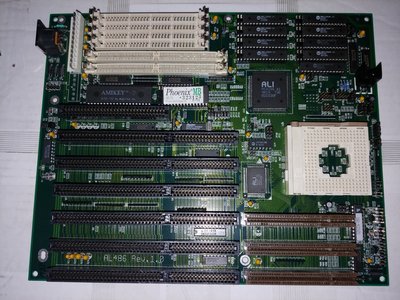
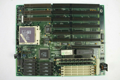
I just received an AL486 Rev. 1.0 like the one here: Need info on AL486 rev1 mobo and opinion for 2 other 486 vlb mobos and I can't locate any documentation for it anywhere either.

I seem to really be striking out with VLB boards. I have two with battery damage, one with a blown tantalum and this one that only needs the voltage regulator resoldered but has no documentation. I have a pile of really nice VLB cards I've been itching to put to use in a 486 but I just can't seem to get a board that is both documented AND fixable\functional.

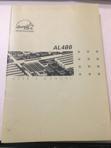
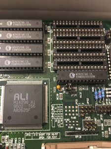
If anyone has a manual or knows of any websites in the dark corners of the internet that might contain such unobtainium, I'd love to see it. If you have one of these boards and it is working, please let us know (preferably with pictures) what your jumper configuration looks like and what CPU you're running, and any information you've gleaned from using it.

Now for some blitting from the back buffer.

Reply 1 of 29, by Ozzuneoj

User metadata
Rank l33t
Rank
l33t

I'm going to bump this because I'm going through my boards again and this is still one of the nicest looking 486 boards I have. Anyone have an AL486 REV. 1.0? Please help!

20190830_134552~01.jpeg
Filename
20190830_134552~01.jpeg
File size
1.64 MiB
Views
1295 views
File license
Fair use/fair dealing exception

Now for some blitting from the back buffer.

Reply 3 of 29, by Horun

User metadata
Rank l33t++
Rank
l33t++
Ozzuneoj wrote on 2020-02-29, 04:51:

Another bump for this nice looking board that I don't want to fry by blindly experimenting with jumpers.

Someone at VCFed asked about similar and said the board is from ECS (Elitegroup Computer Systems). Have you tried to boot up the board ?
Getting the BIOS string may help narrow it down or confirm it is from ECS.

UPDATE: think I found the jumpers but due to your camera angle is hard to read all the JP#.
In the "The PC Engineers Reference Book. Volume 2: Motherboards" under ECS is AL 486(-l). There are no pictures but based on the jumper numbers and locations it appears to be the right docu for your board. (ex: Jp2 is in correct position, jp46 and 62 also, jp33 and jp34 @ cache, etc). Look at Page 200 in this link:
http://www.vogonsdrivers.com/getfile.php?file … 4&menustate=0,0

Hate posting a reply and then have to edit it because it made no sense 😁 First computer was an IBM 3270 workstation with CGA monitor. Stuff: https://archive.org/details/@horun

Reply 4 of 29, by Ozzuneoj

User metadata
Rank l33t
Rank
l33t
Horun wrote on 2020-02-29, 15:59:
Someone at VCFed asked about similar and said the board is from ECS (Elitegroup Computer Systems). Have you tried to boot up the […]
Show full quote
Ozzuneoj wrote on 2020-02-29, 04:51:

Another bump for this nice looking board that I don't want to fry by blindly experimenting with jumpers.

Someone at VCFed asked about similar and said the board is from ECS (Elitegroup Computer Systems). Have you tried to boot up the board ?
Getting the BIOS string may help narrow it down or confirm it is from ECS.

UPDATE: think I found the jumpers but due to your camera angle is hard to read all the JP#.
In the "The PC Engineers Reference Book. Volume 2: Motherboards" under ECS is AL 486(-l). There are no pictures but based on the jumper numbers and locations it appears to be the right docu for your board. (ex: Jp2 is in correct position, jp46 and 62 also, jp33 and jp34 @ cache, etc). Look at Page 200 in this link:
http://www.vogonsdrivers.com/getfile.php?file … 4&menustate=0,0

Thank you so much!

This is the first lead I've had. I'll dig out the board and check the jumpers to see if it looks like a match. I have a feeling this is right though. 😀

I haven't powered the board on because I have very little experience with sockets prior to socket 7 and without any knowledge of the jumpers I didn't want to damage any CPUs or the board.

Now for some blitting from the back buffer.

Reply 5 of 29, by Horun

User metadata
Rank l33t++
Rank
l33t++

I would try a standard 5v Intel 486 cpu like 486Dx-33 or DX2-66 as the board supports 5v, 3.45v and 3.3v cpu. You cannot burn out a 5v 486 cpu with 3.3v so if the jumpers some what match but something else is wrong at least you will not ruin the cpu. Good Luck !
EGAD am such a dork. should have mentioned that if it does work with 5v cpu set at 5v you can change the volts jumpers and check the VRM volts to make sure it does deliver the 3.45 and 3.3v. Should be easy just like checking a Pentium boards VRM.

Hate posting a reply and then have to edit it because it made no sense 😁 First computer was an IBM 3270 workstation with CGA monitor. Stuff: https://archive.org/details/@horun

Reply 6 of 29, by Ozzuneoj

User metadata
Rank l33t
Rank
l33t

Well, I repaired the legs on the VRM and I have set the jumpers to work with a 5V Intel DX2 66Mhz but I can't get the board to do anything. I've tried several different kinds of RAM, tried a couple different CPUs and tried reseating the BIOS chip and some others. Using a POST card I get lights for all of the voltages but no POST code. I wonder if the BIOS chip is dead. That'd probably be very bad for such a hard to locate board...

Now for some blitting from the back buffer.

Reply 7 of 29, by Horun

User metadata
Rank l33t++
Rank
l33t++

That is too bad. Could be bad BIOS chip. You could try the bios chip in a bootable PCI NIC and try to save it with UniFlash. If it saves anything then may be a differant problem. The BIOS off any ALI 1429G + ALI 1431 board may also work. Odd that it has a Phoenix bios and not AMI or Award.

Hate posting a reply and then have to edit it because it made no sense 😁 First computer was an IBM 3270 workstation with CGA monitor. Stuff: https://archive.org/details/@horun

Reply 8 of 29, by Ozzuneoj

User metadata
Rank l33t
Rank
l33t
Horun wrote on 2020-03-01, 23:37:

That is too bad. Could be bad BIOS chip. You could try the bios chip in a bootable PCI NIC and try to save it with UniFlash. If it saves anything then may be a differant problem. The BIOS off any ALI 1429G + ALI 1431 board may also work. Odd that it has a Phoenix bios and not AMI or Award.

It seems odd to me that the 28pin BIOS chip isn't aligned to the notch side on the 32pin socket and is instead pushed to the opposite side. I have a USB EPROM reader so I'll see if the chip will read.

Now for some blitting from the back buffer.

Reply 9 of 29, by maxtherabbit

User metadata
Rank l33t
Rank
l33t
Ozzuneoj wrote on 2020-03-02, 01:06:
Horun wrote on 2020-03-01, 23:37:

That is too bad. Could be bad BIOS chip. You could try the bios chip in a bootable PCI NIC and try to save it with UniFlash. If it saves anything then may be a differant problem. The BIOS off any ALI 1429G + ALI 1431 board may also work. Odd that it has a Phoenix bios and not AMI or Award.

It seems odd to me that the 28pin BIOS chip isn't aligned to the notch side on the 32pin socket and is instead pushed to the opposite side. I have a USB EPROM reader so I'll see if the chip will read.

"pushed away from the notch side" exactly describes the cache and tag chips on all my 486 boards that support using either DIP-32 or DIP-28 SRAMs

Reply 10 of 29, by Ozzuneoj

User metadata
Rank l33t
Rank
l33t
maxtherabbit wrote on 2020-03-02, 01:20:
Ozzuneoj wrote on 2020-03-02, 01:06:
Horun wrote on 2020-03-01, 23:37:

That is too bad. Could be bad BIOS chip. You could try the bios chip in a bootable PCI NIC and try to save it with UniFlash. If it saves anything then may be a differant problem. The BIOS off any ALI 1429G + ALI 1431 board may also work. Odd that it has a Phoenix bios and not AMI or Award.

It seems odd to me that the 28pin BIOS chip isn't aligned to the notch side on the 32pin socket and is instead pushed to the opposite side. I have a USB EPROM reader so I'll see if the chip will read.

"pushed away from the notch side" exactly describes the cache and tag chips on all my 486 boards that support using either DIP-32 or DIP-28 SRAMs

Thanks for the input. I just double checked the pinouts and this is how 28pin EPROMs should be inserted into a 32pin socket. Boy, I bet that has led to many burnt out chips over the years, since there are no markings to indicate that you shouldn't align the notch if you're inserting a smaller EPROM.

With my EPROM reader it seems to work. I don't see much readable text, but it is there. Here is a dump of the ROM. If anyone can see anything interesting here, let me know.

By the way, the chip is an ST M27C512 DIP28.

Attachments

Now for some blitting from the back buffer.

Reply 11 of 29, by Horun

User metadata
Rank l33t++
Rank
l33t++

Thanks for checking the BIOS. One thing caught my eye in it that have not seen before:
"PhoenixBIOS Version 4.03 . Copyright 1987-1994 Phoenix Technologies Ltd., All Rights Reserved.
FOR EVALUATION ONLY. NOT FOR RESALE. <--- **THIS**
Build Time: AL486 V1.1 6/27/1994"

Good news is that it does have lots of processor support:
"486DX.486SX.486DX2.486SX2.486DX4.487SX.386/486.Cyrix Cx486SLC.Cyrix Cx486DLC.IBM 386SLC.IBM 486SLC2.P24T.Pentium.Cyrix Cx486S.Cyrix Cx486S2.Blue Lightning.Cyrix Cx486DX.Cyrix Cx486DX2.UMC U5 GREEN."

Hate posting a reply and then have to edit it because it made no sense 😁 First computer was an IBM 3270 workstation with CGA monitor. Stuff: https://archive.org/details/@horun

Reply 12 of 29, by Ozzuneoj

User metadata
Rank l33t
Rank
l33t

Well, this looks like the correct BIOS chip for this board, I just found one of these that was on ebay and it has the same Phoenix BIOS label on a dip28:

So, if I was able to dump that ROM, then the chip should be fine?

I'm not sure what else to do here.

What would cause a board to show no POST codes?

Attachments

  • al486_on_ebay.jpg
    Filename
    al486_on_ebay.jpg
    File size
    257.31 KiB
    Views
    1110 views
    File license
    Fair use/fair dealing exception
Last edited by Stiletto on 2020-03-02, 05:53. Edited 1 time in total.
Reason: removed eBay link

Now for some blitting from the back buffer.

Reply 13 of 29, by Ozzuneoj

User metadata
Rank l33t
Rank
l33t

Just tried reflowing all of the solder joints on the BIOS socket as well as a couple of the adjacent DIP chips because a few joints looked a bit rough, possibly cracked.

Didn't make a difference.

I just put together a 3xAAA battery pack and attached it to the external battery header too.

Nothing.

I also checked the voltage on the VRM and I'm getting 4.92V.

I tried checking the tantalum caps for any shorts but they seem fine. I'm no electrical engineer so I don't know what this means but I get a "BEEP_BEEEEEEEEEEEEEEEEEEEEEEEEEEEEP" on continuity tests of almost all of the tantalums. The ones that don't do it appear to be connected to jumper headers that are open (so they aren't connected). Now, normally a long beep on a continuity test tells me there's a problem with a tantalum, but I checked the resistance of them too and they're all measuring almost identically. The double beep I'm guessing just means there is a complete circuit. Again, I'm not good with circuits on this level, so this was just something I tested, I have no idea if this was even worth doing. I know that testing caps in circuit is pretty unreliable, but I've seen tantalums fail shorted and it was very easy to test, so I figured it was worth a try. I think the ones on this board are fine, but I'm not 100% sure.

Now for some blitting from the back buffer.

Reply 14 of 29, by Horun

User metadata
Rank l33t++
Rank
l33t++

Without a CPU measure the Ohms of all the PSU connections to ground and write them down. The Tantalums could be bad. I have a 386 board that didn't boot and found the -12v was near 2ohm (which should be impossible unless a short since nothing uses -12v except add-on cards) so unsoldered the two tants on that line and retested and was in megOhm range. Checked both caps and the bigger yellow one was shorted. Anyway Tants can go bad just like Electro's so do not rule them out.

Hate posting a reply and then have to edit it because it made no sense 😁 First computer was an IBM 3270 workstation with CGA monitor. Stuff: https://archive.org/details/@horun

Reply 15 of 29, by Deunan

User metadata
Rank Oldbie
Rank
Oldbie
Ozzuneoj wrote on 2020-03-02, 02:04:

What would cause a board to show no POST codes?

Dead CPU. Or not jumpered properly. Stuck reset line, which might be also related to lack of Power Good signal from the PSU. Corrupted BIOS ROM. Or actual damage to the board, including corrosion (battery spill but also poor storage conditions). In general these issues are next to impossible to properly diagnose without some tools, like scope, and experience. You can still just luck into finding the problem but on a 486 mobo thats... unlikely.

Reply 16 of 29, by Ozzuneoj

User metadata
Rank l33t
Rank
l33t
Horun wrote on 2020-03-02, 03:43:

Without a CPU measure the Ohms of all the PSU connections to ground and write them down. The Tantalums could be bad. I have a 386 board that didn't boot and found the -12v was near 2ohm (which should be impossible unless a short since nothing uses -12v except add-on cards) so unsoldered the two tants on that line and retested and was in megOhm range. Checked both caps and the bigger yellow one was shorted. Anyway Tants can go bad just like Electro's so do not rule them out.

Thanks for the tip!

I just measured all of the P8/P9 connections with my DMM (black lead on ground, testing each pin with red lead), and I get around 200 ohms on all of the +5v leads, where as the -12v, +12v and PG are showing between 1 and 15 Mega Ohms. Does this sound normal?

To power this I am mainly using a 24pin ATX to AT converter (with -5v and a dummy load) on modern power supplies for testing, but I also tested an old Antec 300W 20pin ATX and an Enlight 250W AT. I just tested all three on a Socket 7 AT board and they work fine. On the AL486 I get the same results with any of these power supplies.

Now for some blitting from the back buffer.

Reply 17 of 29, by Ozzuneoj

User metadata
Rank l33t
Rank
l33t

AH!

Welp... All this time I'd had one jumper wrong. The voltage jumpers are kind of crammed together and I misread which was which. After looking at it again I realized I had it in the wrong spot, so I switched it to where it should be to use the 5v from the PSU and it immediately is working! I'm just glad I didn't go replacing anything that wasn't dead.

Woohoo!

This board is in beautiful shape and I'm so glad it is working. Barrel batteries really were a truly horrible idea. This board did not have one (external bat only) and it is the only 486 ISA+VLB board I own that is in working order.

Thanks for the help guys! 😀

Now for some blitting from the back buffer.

Reply 18 of 29, by Horun

User metadata
Rank l33t++
Rank
l33t++

Great !! Glad you got it working !

Ozzuneoj wrote on 2020-03-04, 18:36:

I just measured all of the P8/P9 connections with my DMM (black lead on ground, testing each pin with red lead), and I get around 200 ohms on all of the +5v leads, where as the -12v, +12v and PG are showing between 1 and 15 Mega Ohms. Does this sound normal?

Yes those readings sound good. Shows no shorts ! The +5v is a bit lower than some but that is also board model specific and yes the +12, -5 and -12 should all be very high.

I think I will bundle: your board picture, your bios and create a mini PDF of the jumpers from that book. Then up it to VogonsDrivers in case anyone else needs the info.
If you have anything to add to your work on the board that you found important let me know and we could add that too as a tech note.

Hate posting a reply and then have to edit it because it made no sense 😁 First computer was an IBM 3270 workstation with CGA monitor. Stuff: https://archive.org/details/@horun

Reply 19 of 29, by Ozzuneoj

User metadata
Rank l33t
Rank
l33t

Just wanted to mention, for those interested in archiving obsolete manuals and information, someone just listed a 1.1 revision of one of these AL486 boards, in box with the original manual on a certain popular US auction site. It's way out of my price range, but if anyone has the means or desire to get the board and book and archive the documentation I'm sure it would be appreciated by more than a few people over the years. Being that this is one of the very few VLB (no PCI) boards without a barrel battery, I think these are nice boards to have and will be somewhat more common as more boards succumb to battery corrosion.

It looks like the Rev 1.1 has *drum roll*....... MARKINGS ON IT TO IDENTIFY THE JUMPERS! What an idea... 🤣

Anyway, I just wanted to throw this out there. You don't often see VLB boards with manuals... especially not ones that have very little documentation online AND have features that make them desirable.

Disclaimer: I do not own this board and I do not know who is selling it. I just thought it was a rare opportunity to maybe get more complete information about it before the book ends up in someone's closet for another 25 years.

Attachments

  • s-l16005.jpg
    Filename
    s-l16005.jpg
    File size
    129.56 KiB
    Views
    907 views
    File license
    Public domain
  • s-l16004.jpg
    Filename
    s-l16004.jpg
    File size
    248.95 KiB
    Views
    907 views
    File license
    Public domain
  • s-l16003.jpg
    Filename
    s-l16003.jpg
    File size
    270.12 KiB
    Views
    907 views
    File license
    Public domain
  • s-l16002.jpg
    Filename
    s-l16002.jpg
    File size
    184.38 KiB
    Views
    907 views
    File license
    Public domain
  • s-l1600.jpg
    Filename
    s-l1600.jpg
    File size
    399.23 KiB
    Views
    907 views
    File license
    Public domain

Now for some blitting from the back buffer.