Reply 80 of 101, by Murugan

Rank
Oldbie
- Rank
- Oldbie
Must be then. Data pin shows no trace either. Just a solderblob.
My retro collection: too much...
Must be then. Data pin shows no trace either. Just a solderblob.
My retro collection: too much...
OK, so I am back to working on this motherboard and I thought I may as well resurrect this thread rather than start a new one.. Ahem.
Previously in this thread: I managed to get this board to POST

However:
1. I don't really have a solid understanding of what most of its jumpers do
2. It keeps throwing Keyboard Errors
The original plan was to desolder the 80C42 KBC and install a socket so I can try another KBC chip, but I thought I may as well start re-checking all continuities and while I was at it I drew a circuit diagram of everything I found that was connected to the AT Keyboard port. This is what it looks like:
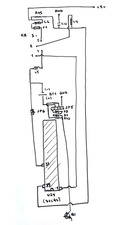
So my understanding is that every single pin on the Keyboard socket is connected to where they should be, so if the board is still giving me issues with the keyboard it can either be:
a) A KBC issue
b) An electrical issue
I can easily test out a) by replacing the KBC, but before I do that, I want to rule out b). Pin 5 IS connected to +5V, is this a good enough verification?
Also, I am trying to make sense of JP5 and JP6 here.
JP6 sits between Pin 33 of 80C42 (P16) which is a readonly register, so I am *assuming* that this is a Color/Monochrome jumper. Anyone disagree here?
JP5 is obviously the EXT_BAT jumper and most important to my purpose, but I am not sure exactly how it works.
Pin 1 is conencted to the circuit via a couple diodes which appear to be there to block a recharging current, so I guess the external battery goes to Pin 1-4
Shorting Pins 2-3 connects the BAT to the circuit via R43 which I suppose is related to recharging somehow?
Shorting Pins 1-2 effectively seems to make the onboard battery behave like an external battery, i.e. no recharging? Not sure if this is intended..
Please do correct me on these 😀 Also, open to all suggestions on how to proceed with this thing.
Once I get these figured out I will try figuring out how JP3/JP4 (Cache related, possibly turning on pipelining?) and JP5/JP6 (Oscillator IC related, probably setting CPU frequency between 20/25/33/40) work..
Retronautics: A digital gallery of my retro computers, hardware and projects.
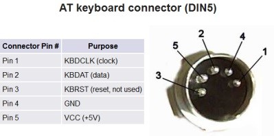
You can connect a external 4.5V battery pack (3 AA in series) on pins 1 and 4 of JP5. This way, you will make use of the internal diode which will prevent charging and drop the voltage down to ~3.6V.
Also, the negative battery terminal should be connected to GND as well in your schematic, because pin 4 of the KB connector is GND (thru a coil).
This means that JP6 actually pulls to Ground pin 33 of the KBC.
Begin by checking voltages on the KB connector all ICs near the battery. If they match, start tracing the CLK and DATA signals, see if there is a compromised trace you haven't found yet.
appiah4 wrote on 2020-05-27, 21:29:OK, so I am back to working on this motherboard and I thought I may as well resurrect this thread rather than start a new one.. Ahem.
1. I don't really have a solid understanding of what most of its jumpers do
This is just a guess but I've seen quite a few of these SX mobos so I'm pretty confident:
- JP6 is mono/color jumper
- JP5 is battery jumper, 2 middle pins are closed to get the on-board NiCd conected but since you have it removed it doesn't matter now. The outer 2 pins are for external pack, just check which one is GND because I've seen those reversed vs the most common pin numbering
There are no other configuration of this jumper, just 2 middle shorted or not, but depending on how it's wired it is sometimes possible to use external rechargeable battery pack with a different configuration - not recommended. Also it seems you have 2 diodes for the external pack so I suggest using 3x AA holder (4x is acceptable too). Or AAA, same thing.
Jumpers next to SIMMs are cache size, the ones next to clock generator are for clock speed. There might be another one (possibly factory soldered or missing) next to NPU socket to select async clocking mode (not sure if OPTi chipset supports this, ALI ones do).
appiah4 wrote on 2020-05-27, 21:29:2. It keeps throwing Keyboard Errors
Pin 1 should have a pull-up to 5V just like pin 2. The resistor for that would normally be somewhere close to R45. Possibly corroded trace or solder pad?
computerguy08 wrote on 2020-05-28, 07:31:You can connect a external 4.5V battery pack (3 AA in series) on pins 1 and 4 of JP5. This way, you will make use of the internal diode which will prevent charging and drop the voltage down to ~3.6V.
I will use a CR2032 battery holder connected to Pins 1/4, let's hope that provides enough juice..
computerguy08 wrote on 2020-05-28, 07:31:Also, the negative battery terminal should be connected to GND as well in your schematic, because pin 4 of the KB connector is GND (thru a coil).
Sockets-AT.jpg
You are absolutely correct (improved circuit diagram below).
computerguy08 wrote on 2020-05-28, 07:31:This means that JP6 actually pulls to Ground pin 33 of the KBC.
Yes and I think this sets a certain bit on the KBC that the BIOS registers as a color graphics adapter..
computerguy08 wrote on 2020-05-28, 07:31:Begin by checking voltages on the KB connector all ICs near the battery. If they match, start tracing the CLK and DATA signals, see if there is a compromised trace you haven't found yet.
I still can't find any...
Deunan wrote on 2020-05-28, 11:18:This is just a guess but I've seen quite a few of these SX mobos so I'm pretty confident: - JP6 is mono/color jumper - JP5 is ba […]
This is just a guess but I've seen quite a few of these SX mobos so I'm pretty confident:
- JP6 is mono/color jumper
- JP5 is battery jumper, 2 middle pins are closed to get the on-board NiCd conected but since you have it removed it doesn't matter now. The outer 2 pins are for external pack, just check which one is GND because I've seen those reversed vs the most common pin numbering
There are no other configuration of this jumper, just 2 middle shorted or not, but depending on how it's wired it is sometimes possible to use external rechargeable battery pack with a different configuration - not recommended. Also it seems you have 2 diodes for the external pack so I suggest using 3x AA holder (4x is acceptable too). Or AAA, same thing.
I am planning to connect a CR2032 coin cell holder to pins 1/4, you reckon it would be enough?
Deunan wrote on 2020-05-28, 11:18:Jumpers next to SIMMs are cache size, the ones next to clock generator are for clock speed. There might be another one (possibly factory soldered or missing) next to NPU socket to select async clocking mode (not sure if OPTi chipset supports this, ALI ones do).
I figured as much, I suppose finding out shorting which does what will take some trial and error...
Deunan wrote on 2020-05-28, 11:18:Jin 1 should have a pull-up to 5V just like pin 2. The resistor for that would normally be somewhere close to R45. Possibly corroded trace or solder pad?
You, sir, are absolutely correct. Updated circuit diagram below:

Every single one of these traces work 100%. Where else do I look on the board that could cause a Keyboard Error at boot? Possibly something's wrong with the 5V rail?
Retronautics: A digital gallery of my retro computers, hardware and projects.
Regarding JP3/JP4, Pin 1 of each jumper is connected to Pin 65 and Pin 66 on the 386SX CPU respectively (A14 and A15); what could they be doing? I couldn't trace the other pins to any other component yet..
Retronautics: A digital gallery of my retro computers, hardware and projects.
appiah4 wrote on 2020-05-28, 16:04:I will use a CR2032 battery holder connected to Pins 1/4, let's hope that provides enough juice..
That is a bit on the low side, the CR2032 only has 3V, passing it trough the diode will lower the voltage even more. It may work, but don't get surprised if you see a CMOS checksum error.
computerguy08 wrote on 2020-05-28, 18:45:appiah4 wrote on 2020-05-28, 16:04:I will use a CR2032 battery holder connected to Pins 1/4, let's hope that provides enough juice..
That is a bit on the low side, the CR2032 only has 3V, passing it trough the diode will lower the voltage even more. It may work, but don't get surprised if you see a CMOS checksum error.
From my experience the RTC will not update, but it usually holds the CMOS data...
Is the trace between R46 and C11 ok? From the picture it seems not to reach R46.
Also, your boot screen has (partly) identified the board:
30-0200-001107-00001111-121291-OPTX 291-0 / OPTI-291WB BIOS VER 1.2
001107 -> DataExpert and OPTI-291WB would be a plausible model name seeing they have a OPTI-495SX etc as model name. Now for some jumper settings...
root42 wrote on 2020-05-28, 20:11:From my experience the RTC will not update, but it usually holds the CMOS data...
What do you mean by "RTC will not update"? Date/Time will reset but CMOS settings will stick?
evasive wrote on 2020-05-28, 20:36:Is the trace between R46 and C11 ok? From the picture it seems not to reach R46. […]
Is the trace between R46 and C11 ok? From the picture it seems not to reach R46.
Also, your boot screen has (partly) identified the board:
30-0200-001107-00001111-121291-OPTX 291-0 / OPTI-291WB BIOS VER 1.2001107 -> DataExpert and OPTI-291WB would be a plausible model name seeing they have a OPTI-495SX etc as model name. Now for some jumper settings...
Ah, excuse my sketch - the trace is fine and yes R46 and C11 are connected.
Thanks for the board identification too!
Retronautics: A digital gallery of my retro computers, hardware and projects.
appiah4 wrote on 2020-05-28, 22:02:root42 wrote on 2020-05-28, 20:11:From my experience the RTC will not update, but it usually holds the CMOS data...
What do you mean by "RTC will not update"? Date/Time will reset but CMOS settings will stick?
The RTC lags on my board or just doesn't update when the machine is powered off using a 3V + diode.
Yes, when there's a couple of diodes after the ext. battery connector I've had the same behavior as root42 if using a 3V coin cell... CMOS settings persist, but the RTC stops ticking after power off. Swapping to 3xAAAs or 3xAAs to up the voltage to 4.5V usually does the trick.
Regarding the keyboard error, appiah4, I think desoldering the KB controller chip would also allow you to check traces that run under the chip and may be corroded even though the chip itself is OK. So I would do that (assuming you have the adequate desoldering tools of course).
IF the chip is indeed the problem, you could try to replace it with a similar one, but I always wondered if these 80C42 are all interchangeable... also keep in mind that installing a socket there may block the ISA cards on the nearby slots in some cases.
appiah4 wrote on 2020-05-28, 16:04:I am planning to connect a CR2032 coin cell holder to pins 1/4, you reckon it would be enough?
Probably not. That's sketchy with 1 diode and I'd say with 2 like you have it might not work at all or the RTC will lag a lot. And that's on good new coin cell, once it discharges a bit it'll be even worse. Though it has to be said these type of cells have a pretty flat voltage curve right until they die.
appiah4 wrote on 2020-05-28, 16:04:Every single one of these traces work 100%. Where else do I look on the board that could cause a Keyboard Error at boot? Possibly something's wrong with the 5V rail?
Well, I've recently had a mobo that had a lot of corrosion that I've repaired but it still wouldn't see the keyboard. Turns out the connector itself got correded too and I had to use a small round file to clean the oxidation - though that'll probably not last and oxidize again, so I should replace it. Well, if I cared for that mobo at all.
If you have "big" DIN to small PS/2 adapter then shove that in and test on the solder points from one side and the PS/2 on the other side. That'll tell you if you have a good connection inside the DIN socket or not.
Do you get a blink on the keyboard LEDS on power-on? Can you enable NumLock or other *lock keys that have a LED indicator?
Thanks @root42, @TheMobRules and @Deunan. Instead of quoting you all separately I thought I'd make a single shorter post..
Regarding the battery, thanks about the dual diode heads up, I will forego the CR2032 and instead go with this thing I found in my battery box that my obsessive harder half appears to have bought at some point (To be honest that half of me impulsively buys such strange junk so often that I forget about them a lot, but they are often pleasant surprises like this when they turn up 😀 )
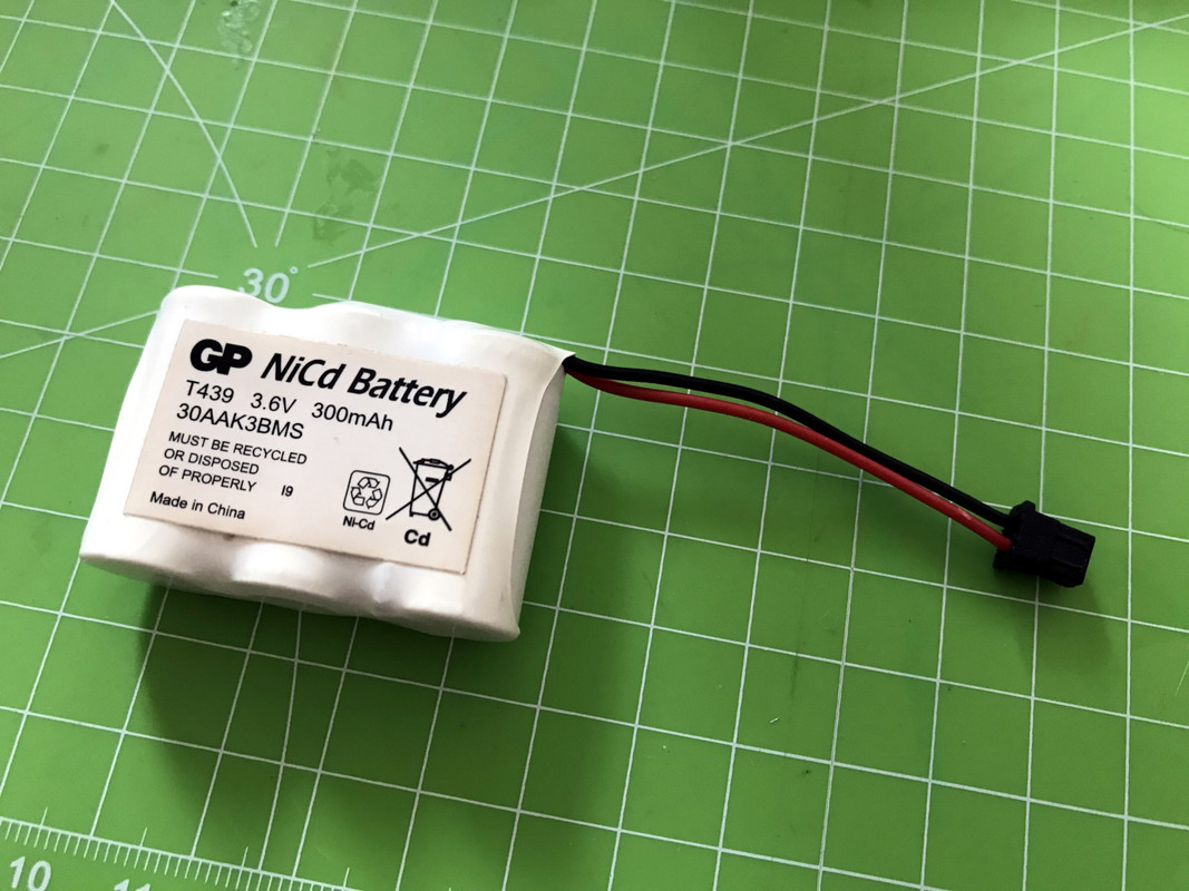
3.6V should be enough, I would think. Moreover, it's a NiCd rechargable so I can actually wire it to the BAT1 circuit and allow it to recharge? Pin 2 of JP5 (EXT_BAT) header is shorted to Pin 3 for BAT1 use, so I thought I could directly connect it to Pin 3-4 on the JP5 (EXT_BAT) header and use it like this:
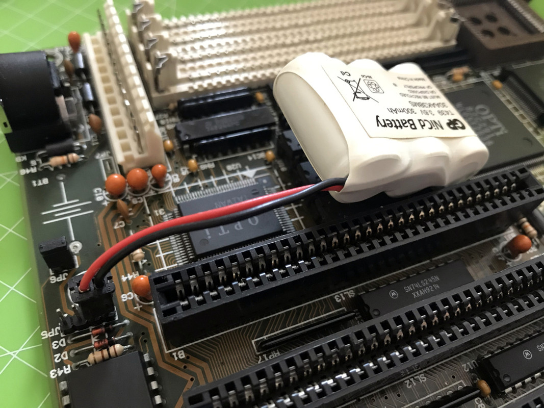
Correct?
Regarding checking under the KBC for broken traces - yes, I will do this, but I want to remove the KBC as a last resort as I will do it with a simple desoldering pump and solder wick, and while I had some success with removing Dallas RTCs in the past I don't look forward to cleaning 40 THT holes 🙁
Regarding keyboard behavior, when I turn the system on I get a single blink on Caps/Scroll/Num lock but after that the keyboard is semi-nonresponsive. When I get Keyboard Error, pressing any key on the keyboard produces a BEEP from the PC Speaker and nothing else.
I went back and re-read my own thread, and apparently @Tiido suggested it may be a broken trace between the CPU and the KBC which possibly goes through 74x244 or 74x245chips nearby. Apparently I left off at this point before checking continuity of all Data, Address, Read/Write Strobe, and Clock Signal pins . I will need more handholding with this I am afraid. 🙁
Only after this is done will I desolder the KBC..
Retronautics: A digital gallery of my retro computers, hardware and projects.
appiah4 wrote on 2020-05-29, 07:31:3.6V should be enough, I would think. Moreover, it's a NiCd rechargable so I can actually wire it to the BAT1 circuit and allow it to recharge?
3V6 is what the original battery was so yes, it will work, though this one is bigger and will require some more up-time from the PC to fully charge. It too can leak and will have significant self-discharge (like all NiCd/NiMH do) - unlike the AA(A) packs that can last a decade with quality cells. Also NiCds do have a "memory effect" - this is crystals forming in the cell when it's not fully charged and then almost fully discharged once in a while. That will eventually internally short and kill it.
So, short term you can use that pack with good results but remove it for long-term storage or even for perdiods of not being daily used.
appiah4 wrote on 2020-05-29, 07:31:Regarding keyboard behavior, when I turn the system on I get a single blink on Caps/Scroll/Num lock but after that the keyboard is semi-nonresponsive. When I get Keyboard Error, pressing any key on the keyboard produces a BEEP from the PC Speaker and nothing else.
That means the KBC to keyboard connection is fine, it's the KBC to system link that's faulty. Most likely one of the data lines (should be pins 12-19). Or the KBC itself is toast but that's rare occurence.
Deunan wrote on 2020-05-29, 13:40:3V6 is what the original battery was so yes, it will work, though this one is bigger and will require some more up-time from the PC to fully charge. It too can leak and will have significant self-discharge (like all NiCd/NiMH do) - unlike the AA(A) packs that can last a decade with quality cells. Also NiCds do have a "memory effect" - this is crystals forming in the cell when it's not fully charged and then almost fully discharged once in a while. That will eventually internally short and kill it.
So, short term you can use that pack with good results but remove it for long-term storage or even for perdiods of not being daily used.
All noted.
Deunan wrote on 2020-05-29, 13:40:That means the KBC to keyboard connection is fine, it's the KBC to system link that's faulty. Most likely one of the data lines (should be pins 12-19). Or the KBC itself is toast but that's rare occurence.
I will check all traces from Pins 12-19 of the 80C42 tonight, then we'll know whether it's a broken trace or the KBC is toast.. 😎
Retronautics: A digital gallery of my retro computers, hardware and projects.
There are quite a few Lithium based 3.6V batteries that could be an option:
https://duckduckgo.com/?q=saft+3.6v+battery&t … ng&iax=shopping#
They are not cheap, though.
root42 wrote on 2020-05-29, 14:32:There are quite a few Lithium based 3.6V batteries that could be an option:
https://duckduckgo.com/?q=saft+3.6v+battery&t … ng&iax=shopping#
They are not cheap, though.
I do have one AA sized 3.6V Li battery but no 1xAA holder at the moment.. So the NiCd for the moment will do. (I apparently have a NiMh version of the same wireless phone battery pack as well 🤣, I'm a terrible hoarder..)
Retronautics: A digital gallery of my retro computers, hardware and projects.
root42 wrote on 2020-05-29, 14:32:There are quite a few Lithium based 3.6V batteries that could be an option:
https://duckduckgo.com/?q=saft+3.6v+battery&t … ng&iax=shopping#
They are not cheap, though.
A battery holder and 3 AAs are dirt cheap and, in my opinion, the best choice.
Given the two diodes in the circuit, they will work perfectly.
Deunan wrote on 2020-05-28, 23:27:If you have "big" DIN to small PS/2 adapter then shove that in and test on the solder points from one side and the PS/2 on the other side. That'll tell you if you have a good connection inside the DIN socket or not.
Oh, and I forgot to say - Yes, I have one of these adapters, and there is good contact on all 4 relevant pins.
Retronautics: A digital gallery of my retro computers, hardware and projects.


