VOGONS


First post, by Jo22

User metadata
Rank l33t++
Rank
l33t++

Hi everyone, I have got some trouble with an XT clone and I am seeking for help.
Maybe some of you have a clue what to do ?

Any idea what causes the -12v line to go away the most ?

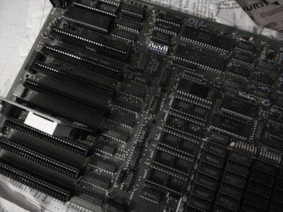
The mainboard is a replica/clone of that popular 8Mhz Turbo clone ("8 MHZ TURBO BOARD").

- There is no POST on the keyboard (works in another XT PC).
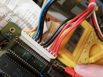
- I have checked the power and it seems that the -12 line on ISA has no power.

- I also swapped both the power supply and the 8088 processor against another model.
- I also installed an ISA VGA card (no picture).

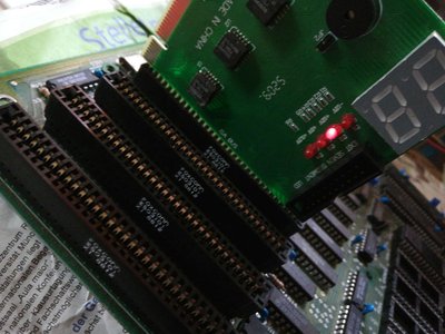
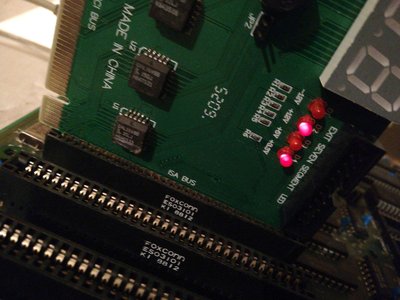
Unfortunately, the ISA POST card is of little help. It works in PC/AT class systems only. 🙁
The XT POST codes are simply to old or different to be understood by it.

Any help welcome! ::

PS: I have dumped the BIOS of the board, since I suspected it to be faulty (still not entirely sure).
However, I got readable ASCII signs in a hex editor.. So is this BIOS okay perhaps ? 😕

Attachments

  • turbo_postcard.jpg
    Filename
    turbo_postcard.jpg
    File size
    268.15 KiB
    Views
    900 views
    File license
    Fair use/fair dealing exception
  • turbo_mb.jpg
    Filename
    turbo_mb.jpg
    File size
    301.1 KiB
    Views
    900 views
    File license
    Fair use/fair dealing exception
  • Filename
    bios_turbo_xt.zip
    File size
    6.29 KiB
    Downloads
    31 downloads
    File license
    Fair use/fair dealing exception

"Time, it seems, doesn't flow. For some it's fast, for some it's slow.
In what to one race is no time at all, another race can rise and fall..." - The Minstrel

//My video channel//

Reply 1 of 33, by SSTV2

User metadata
Rank Oldbie
Rank
Oldbie

I had similar situation not too long ago of one of the 12V voltage lines missing in the ISA slots, which caused serial mouse to be undetectable, but otherwise 486 MB was fully functional. I'm not sure how -12V line is important for an XT motherboard to work, but if -12V is present at PSU, but not in ISA slots, it most likely means that AT power header had corroded.

Measure resistance between +5V and GND at power header.

Reply 2 of 33, by Jo22

User metadata
Rank l33t++
Rank
l33t++

Thank you very much for your reply and the tip! 😀

I' have checked the voltages on what looks like a testing pad..
All voltages are there, so I guess both the contacts and the power supply are fine at least.

Attachments

  • turbo_pad-12v.jpg
    Filename
    turbo_pad-12v.jpg
    File size
    241.02 KiB
    Views
    855 views
    File license
    Fair use/fair dealing exception

"Time, it seems, doesn't flow. For some it's fast, for some it's slow.
In what to one race is no time at all, another race can rise and fall..." - The Minstrel

//My video channel//

Reply 3 of 33, by sf78

User metadata
Rank Oldbie
Rank
Oldbie

You have several tantalum caps on the mainboard, those are notoriously unreliable as they age and don't show any symptoms of failing until they explode to your face. Many XT boards have them and most require replacement by now. Fortunately, they can be measured while still soldered in so it's a quick check and very easy to fix by just cutting the legs of the old one and soldering in a new replacement. Just make sure you orient them the right way around (+ and -).

Reply 4 of 33, by Jo22

User metadata
Rank l33t++
Rank
l33t++

I see.. Do I have to check/replace the yellow ones (10µF 15v unipolar ?) only or the blue ones (mainly 0.1µF aka 100nF ?), too ?
And if I have to replace them, can I use electrolytic types instead ?

"Time, it seems, doesn't flow. For some it's fast, for some it's slow.
In what to one race is no time at all, another race can rise and fall..." - The Minstrel

//My video channel//

Reply 6 of 33, by Jo22

User metadata
Rank l33t++
Rank
l33t++

Aw, I already cut one of each's yellow cap's leg. Now the other voltage is gone, too. 🙁

Attachments

  • turbo_-5v_gone.jpg
    Filename
    turbo_-5v_gone.jpg
    File size
    276.45 KiB
    Views
    821 views
    File license
    Fair use/fair dealing exception

"Time, it seems, doesn't flow. For some it's fast, for some it's slow.
In what to one race is no time at all, another race can rise and fall..." - The Minstrel

//My video channel//

Reply 8 of 33, by Jo22

User metadata
Rank l33t++
Rank
l33t++

You are right. 😳 Just checked the ISA bus directly and according to the multimeter, all voltages are there.
Though, I do not know how much current flows through these pins. A real power-consuming component like an LED would be nice.
- The keyboard is also still dead (none of the lights flash during POST). I guess I will need to attach a speaker, as well.

"Time, it seems, doesn't flow. For some it's fast, for some it's slow.
In what to one race is no time at all, another race can rise and fall..." - The Minstrel

//My video channel//

Reply 9 of 33, by Jo22

User metadata
Rank l33t++
Rank
l33t++

Okay, so I attached an old PC speaker.. No beep tones. 🙁

"Time, it seems, doesn't flow. For some it's fast, for some it's slow.
In what to one race is no time at all, another race can rise and fall..." - The Minstrel

//My video channel//

Reply 10 of 33, by Deksor

User metadata
Rank l33t
Rank
l33t

You cannot make a device to test the power consumption between two spots that would fit in a ISA slot as far as I know. The only thing you can do is to put the multimeter between the two parts of the PSU connector. That's the only way I know (and probably that exist except induction) to measure the flow of current going through a circuit.

You might also want to measure the resistance between GND and +/- pins. If it's really low (I think 100ohm would be considered as very low, but don't quote me on that), there's probably some other bad caps.

You might also want to reseat the chips just in case.

Trying to identify old hardware ? Visit The retro web - Project's thread The Retro Web project - a stason.org/TH99 alternative

Reply 11 of 33, by Jo22

User metadata
Rank l33t++
Rank
l33t++

Thanks. So I guess I have to continue to tink a bit of this issue for a while.
My main area of concern is the fact that the multimeter might be of too high-impedance.
The measurement shows voltage, were a real device would not get anything meaningful out of it.

"Time, it seems, doesn't flow. For some it's fast, for some it's slow.
In what to one race is no time at all, another race can rise and fall..." - The Minstrel

//My video channel//

Reply 12 of 33, by PC@LIVE

User metadata
Rank Oldbie
Rank
Oldbie

Hi, even if I have not had direct experiences with the MB XT, I could suggest you a line check, in this way you could find if even some other voltage is not ok.
It is very simple, with the MB disconnected from the PSU (therefore P8 and P9 disconnected), put the black tip where in P8 there is a black wire (N ° 5 or N ° 6), and with the red tip measure (OhmX1 ) values.
With this system I found on the Asus MEZ-M an infinity value in the + 3.3V, and in other MB other problems in other lines.
It is a system that also works to repair PSUs, in which case I use a tester set on the diode test with an audible alarm.

AMD 286-16 287-10 4MB HD 45MB VGA 256KB
AMD 386DX-40 Intel 387 8MB HD 81MB VGA 256KB
Cyrix 486DLC-40 IIT387-40 8MB VGA 512KB
AMD 5X86-133 16MB VGA VLB CL5428 2MB and many others
AMD K62+ 550 SOYO 5EMA+ and many others
AST Pentium Pro 200 MHz L2 256KB

Reply 13 of 33, by Jo22

User metadata
Rank l33t++
Rank
l33t++

Thanks, I will try this, too! 😀 - I will also re-install new caps (to replace the ones I did cut off).
Maybe this will bring back the "3.3v" LED to life (it checks 5v if installed in ISA slots, actually).

PS: Just out of curiosity, does anybody know which components of an XT system are prone to fail or are known to use -12v.
- The serial port uses +12v/-12v, I remember. But the XT board has no USART ob-board, so it does not matter.

"Time, it seems, doesn't flow. For some it's fast, for some it's slow.
In what to one race is no time at all, another race can rise and fall..." - The Minstrel

//My video channel//

Reply 14 of 33, by PC@LIVE

User metadata
Rank Oldbie
Rank
Oldbie

Installing new capacitors could restart the MB.
In the past it worked on a VGA VLB GD5424, after checking them with my ESR70, I found values ​​slightly above those printed, at which point I changed them to new ones, and it restarted.
However, about the POST CARD ISA, I'm pretty sure (but I could be wrong ???) that in the MB there is no + 3.3V.
I remember the POST CARDS of the 90s, among these was the RACER II, perhaps they are not to be found because they probably cost a lot.
However if you know the exact model of the original MB, it is likely that you can find the service manual, so at least you might know what the -12V circuits are.

AMD 286-16 287-10 4MB HD 45MB VGA 256KB
AMD 386DX-40 Intel 387 8MB HD 81MB VGA 256KB
Cyrix 486DLC-40 IIT387-40 8MB VGA 512KB
AMD 5X86-133 16MB VGA VLB CL5428 2MB and many others
AMD K62+ 550 SOYO 5EMA+ and many others
AST Pentium Pro 200 MHz L2 256KB

Reply 15 of 33, by PC@LIVE

User metadata
Rank Oldbie
Rank
Oldbie

found a manual for an 8 MHz turbo board, located here:
http://minuszerodegrees.net/manuals/Turbo-XT% … ion%20Guide.pdf
In addition to the jumper settings, you will find connection diagrams.

AMD 286-16 287-10 4MB HD 45MB VGA 256KB
AMD 386DX-40 Intel 387 8MB HD 81MB VGA 256KB
Cyrix 486DLC-40 IIT387-40 8MB VGA 512KB
AMD 5X86-133 16MB VGA VLB CL5428 2MB and many others
AMD K62+ 550 SOYO 5EMA+ and many others
AST Pentium Pro 200 MHz L2 256KB

Reply 16 of 33, by retardware

User metadata
Rank Oldbie
Rank
Oldbie

Many old power supplies do not have overcurrent protection.
If a tantalum shorts, this can lead to burning the trace(s) on the board, as they are often thin and function as fuse.
What resistance is between the P8/P9 post and the ISA -12V line?

Reply 17 of 33, by ShadowGun92

User metadata
Rank Newbie
Rank
Newbie

I would reccomend to solder a wire under the -12v pin of the ISA slot then connect it to the -12v on the power supply... maybe it will run... I have a pentium 3 system with some busted diodes I think because I hadn't +12v whatsoever on the mainboard.. but in the underside of the board I soldered a wire from the +12v connection on the ATX connector to the +12v connection on the fan header and the board sprang to life and always functioned correctly 🤣

Reply 18 of 33, by Deksor

User metadata
Rank l33t
Rank
l33t

Nothing on the board uses -12V so even if -12v is faulty the board should turn on.

Trying to identify old hardware ? Visit The retro web - Project's thread The Retro Web project - a stason.org/TH99 alternative