VOGONS


First post, by dicky96

User metadata
Rank Member
Rank
Member

Hi guys
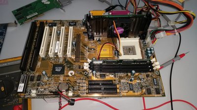
I have this P6BAT-A+ motherboard I am trying to get working

With a known good ATX PSU, and I am pretty sure all the jumpers in the right position, when I press the Power_On button I get a green LED illuminating on the motherboard and a single click from the speaker. That's it - no POST, no beep codes and no obvious sign of life. The CPU fan does not spin. There is 5V on the yellow lead to the fan and 0V on the other two leads.

There are No beeps without RAM and/or AGP card fitted either. I know the AGP card (Geforce 2MX) is good. All the motherboard capacitors look visually OK.

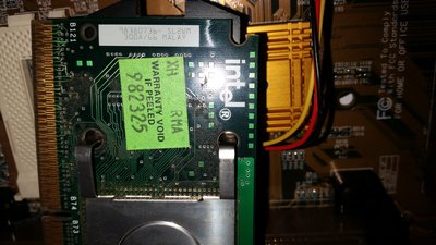
I am testing with a slot 1 Celeron SL2WM 300A/66 CPU. This is the only slot 1 CPU I have (and I have no socket 370) and I bought it from ebay cheap so I can use it to test Slot 1 boards. It's the first time I used it so I can't swear for sure that it is good - though it was sold as a good working CPU. I set the motherboard jumpers to auto select 66/100MHz.

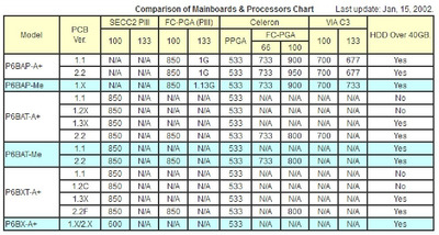
According the the user manual this motherboard supports PII and PIII Slot 1 CPUs, and Socket 370 Celeron CPUs. It does not mention Slot 1 Celeron CPUs, This confuses me a bit and I can't be sure I have a compatible processor fitted?

I also don't have any 100MHz or 66MHz DDR available, Only PC133, of which I have several sticks but I only tried 2 of them.

User Manual is here http://www.ecs.com.tw/ECSWebSite/Product/Prod … 70-LL-Intel-RR-
maybe that's the wrong revision board, mine could be 1.3B

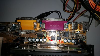
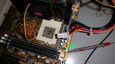
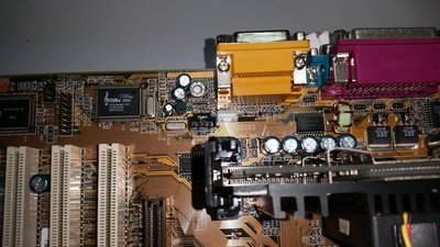
I've checked a few voltages, see attached Pics.

If i understand this right I have CPU power (2V) and RAM power (1.8V) present on the motherboard plus 3.3V ,5V and 12V present on the ATX connector.

Both the CPU and the RAM get mildly warm after a little while so I am pretty sure they have some power at least..

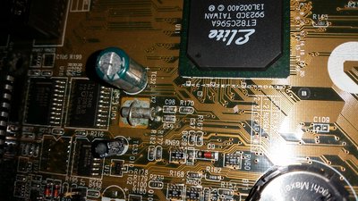
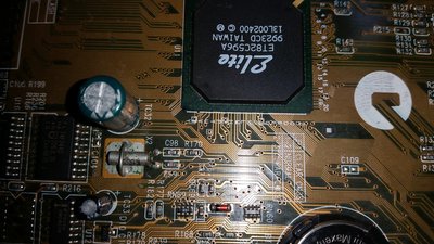
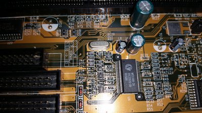
There is some corrosion around a crystal marked X2 on the PCB so that could be the problem? I can't see the crystal frequency markings without unsoldering it.

The attached pics should help clarify what voltages I have measured.

So basically, is this CPU compatible with the motherboard? is PC133 compatible? and are those voltages looking OK?

If so I will concentrate on the Crystal. I'm not sure if the frequency would be too high to see anything on my oscilloscope, but I can try.

Rich

Attachments

  • 20190627_141034.jpg
    Filename
    20190627_141034.jpg
    File size
    1.05 MiB
    Views
    1580 views
    File license
    Fair use/fair dealing exception
  • 20190627_140950.jpg
    Filename
    20190627_140950.jpg
    File size
    1.32 MiB
    Views
    1580 views
    File license
    Fair use/fair dealing exception
  • 20190627_140932.jpg
    Filename
    20190627_140932.jpg
    File size
    1.05 MiB
    Views
    1580 views
    File license
    Fair use/fair dealing exception
  • 20190627_140925.jpg
    Filename
    20190627_140925.jpg
    File size
    964.52 KiB
    Views
    1580 views
    File license
    Fair use/fair dealing exception
  • 20190627_140908.jpg
    Filename
    20190627_140908.jpg
    File size
    1.07 MiB
    Views
    1580 views
    File license
    Fair use/fair dealing exception

Reply 1 of 10, by dicky96

User metadata
Rank Member
Rank
Member

Ok, so I cleaned up the corrosion around that crystal 'X2' and it oscillates. The period is 30uS which makes it 33.333KHz and that seems like a rather low frequency to find on a motherboard. I can't see any frequency markings on the crystal just a marking KDS9E

Maybe if I unsolder it there are markings on the other side

There are two crystals near the back of the PCB close together and they do oscillate. One is 14,31818

There is another 14.31818 near the RAM slots (X1) and that appears not to be oscillating. Near that one is a chipW83194R-39 which is a 100MHxz clock synthesizer and there is oscillation on some of the pins though I need to check more thoroughly - I just got the datasheet.

Looking at the BIOS eprom I would expect to see activity on the pins (Bus activity) but I don't The lines just go to 0V or 3.3V and sit there

It's as though the CPU isn't running. Also with no DIMMs inserted and can't see activity on the DDR socket pins though I only checked some of them

Any ideas what I should check next. I've never gone into any in depth motherboard repair before, just replaced caps - but I thought it was about time I learned.

Rich

Attachments

  • 20190628_144044.jpg
    Filename
    20190628_144044.jpg
    File size
    1.36 MiB
    Views
    1549 views
    File license
    Fair use/fair dealing exception
  • 20190628_144035.jpg
    Filename
    20190628_144035.jpg
    File size
    1.3 MiB
    Views
    1549 views
    File license
    Fair use/fair dealing exception
  • 20190628_143948b.jpg
    Filename
    20190628_143948b.jpg
    File size
    1.3 MiB
    Views
    1549 views
    File license
    Fair use/fair dealing exception

Reply 2 of 10, by Warlord

User metadata
Rank l33t
Rank
l33t

I check the manual for bus speed it says there is either normal or 100 mhz there is no auto. Looks like you have that jumpered correct by the picture. JP4 short 1-2 for 66 short 2-3 to force 100 mhz. There are no other jumpers as far a frequency i can tell. And ya the corrosion looks bad you should replace that.

"There is some corrosion around a crystal marked X2"

That could be your problem there. All of the corrosion needs to be fixed that crystal needs changed and I noticed some other corrosion behind it on that pic near another chip.

Reply 3 of 10, by dicky96

User metadata
Rank Member
Rank
Member

Thanks for the reply

Yes i did set the Jumper for 1-2 which Im sure the manual says auto selects 66/100MHz depending on the processor type - Ill check to see if I imagined that.

The crystal with the corrosion is oscillating with a period of approx 30uS but I can desolder it and see if there is any other markings on it. You can see on second set of pics that area is a lot cleaner now

I would like to know for sure that the Slot 1 Celeron is for sure compatible with this board

Another thought i had is that there is probably one of the ICs that controls the processor reset line and maybe I should look at that area?

rich

Reply 4 of 10, by dicky96

User metadata
Rank Member
Rank
Member

I removed the Crystal X2 and the legs fell off. I've now cleaned the area around the crystal that was corroded. A quick google tells me that this Crystal, marked KDS9E is 32.768KHz. So it was working anyway, on my oscilloscope I could see it was oscillating at about 33KHz. It turns out that this frequency is used by the RTC. Fortunately I can get replacements very easily and cheap.

I then had another look at X1 which is 14.31818MHz. This didn't seem to be oscillating but I could see plenty of oscillation on the pins of theW83194R-39 which is very close to that Crystal X1. The W8194R-39 datasheet says it is a 100MHZ 3-DIMM CLOCK FOR VIA MVP4 which made me think that X1 was connected to that. http://pdf.datasheetcatalog.com/datasheet/Win … ics/mXuuvst.pdf

I removed X1 and the oscillations on W8914R-39 stopped. So I have to assume that X1 is actually oscillating.

I'm not sure where to go next. I did find a pinout for the Slot 1 connector - maybe looking at some of the pins there (Reset, Clock, IRQ etc) would be the next thing to check?

I'm a bit out of my experience here. Can anyone more experienced in motherboard repair give me some pointers? It's like I have a CPU and RAM with power, clocks are running, but nothing is happening.

Thanks
Rich.

addendum
I just had a look at the W83149R-39 datasheet and the CPUCLK_F, CPUCLK1 and CPU_STOP signals must be worth a look

Reply 5 of 10, by dicky96

User metadata
Rank Member
Rank
Member

OK guys - I had a success with this one!

I have just bought an EPROM programmer and I read the contents from the BIOS chip and then compared the bin file to all the versions I could find on the ECS website. It was closest to the V3.0 but it had some differences here and there. So I programmed the later V5.6 BIOS file into the chip - and the motherboard now works great 😁 😁 😁

The BIOS chip is a AE29F2008-12 and my programmer didn't have that on it's device list but I googled it and it said it is the same as a Winbond W29C020 so I chose that option and it read, erased and programmed just fine.

I'll be putting the motherboard on ebay when I next go to the UK. I don't need it and I only paid 5 euros for it so the profit will go a good way towards paying towards the cost of the TL866A programmer.

Needless to say I am well pleased, it's the first time I used the TL866A and i had a success already. Yayy! I also gained some useful experience of motherboard repair.

Actually does anyone know what is the fastest skt370 PIII this board will support? I can find the CPU list for V2.0 but this is a V1.3

Rich

Reply 6 of 10, by dj_pirtu

User metadata
Rank Member
Rank
Member

Hi!

Just got myself the same motherboard but it's revision 2.0 and P3's should work. I have P3-800 and Celeron 667 but either of those just dont work. No picture. Slot1 CPUS's works with no problem. Jumpers are in check, bios is newest 5.6.

Reply 7 of 10, by darry

User metadata
Rank l33t++
Rank
l33t++
dj_pirtu wrote on 2020-11-11, 15:04:

Hi!

Just got myself the same motherboard but it's revision 2.0 and P3's should work. I have P3-800 and Celeron 667 but either of those just dont work. No picture. Slot1 CPUS's works with no problem. Jumpers are in check, bios is newest 5.6.

If you are using a slotket (socket 370 to slot 1 adapter), are you sure that it is compatible with Coppermine CPUs?

Reply 8 of 10, by PC Hoarder Patrol

User metadata
Rank l33t
Rank
l33t
ECS P6Bx CPU Chart.jpg
Filename
ECS P6Bx CPU Chart.jpg
File size
147.05 KiB
Views
1217 views
File license
Fair use/fair dealing exception

https://web.archive.org/web/20020203074314/ht … q/table-p6b.htm

Think v2.0 & v2.2 have the same cpu support level