The only really fool-proof way is to trace the circuit. It's usually not that hard.
Find the '-' side of the battery, make sure that's tied to Gnd by using a multi-meter and checking for continuity between the battery '-' pin and the PSU connector or a shield or the ring around one of the mounting holes. This should always be the case, but it doesn't hurt to make sure. It only takes a second.
Next, put your '+' probe on the +5V pin on the PSU connector. Put the '-' probe on the battery '+' connector. It may have a small resistance (30-200 ohms) or it may be a diode drop -- which your meter might not be able to read. If you don't get a reading that makes sense, follow the trace on the top and/or bottom of the PCB and see where it goes.
If you have to, just put your meter in continuity mode and brush one probe over the pins of components in the area until you get a beep. This is useful for small SMD parts or when traces go under other things. It shouldn't take long to map out all the parts that connect to each other, since there's not much to these circuits.
Make a drawing as you go, and sketch out what connects to what. When you get to the trace that leads off into the weeds, it probably goes to the crystal oscillator circuit and/or the chipset. You should be able to verify that it heads off toward something that looks like a watch crystal or the main guts of the motherboard. That ought to be enough to assume that you've found the CMOS / RTC power line.
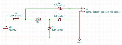
Here's an example from mine:
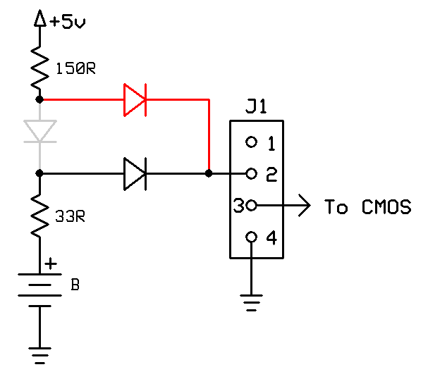
(The gray part is original, the red is my modification to make it safe for an alkaline coin cell.)