VOGONS


HP Kayak XM600 troubleshooting

Topic actions

First post, by Con 2 botones

User metadata
Rank Member
Rank
Member

Hello everyone!

My name´s William and this is my first post. I love retro hardware in general (PC and gaming consoles), but when it comes to PC I have special devotion for 1997-2001 era. 😊

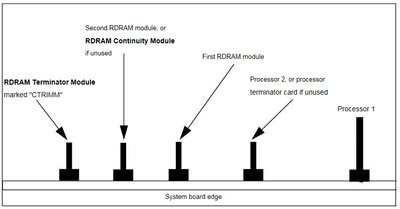
I´ve recently acquired an ASUS P3C-D motherboard, that later found out belongs to a HP Kayak XM-600 workstation. It´s a dual slot 1, RIMM (RDRAM) based, intel 820 chipset motherboard.

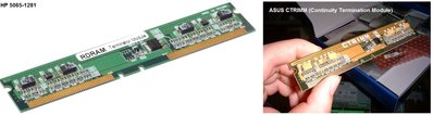
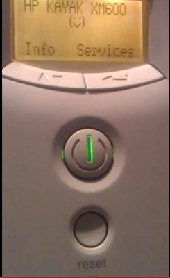
The purchase included a PIII 600mhz (133mhz bus) CPU, a RIMM module, the needed continuity module, the original PSU and also a small "box" which contains a display and the power & reset switches. Under normal circumstances this "box" is attached to the front of the original cabinet (which I don´t own), connected internally (proprietary connector) to the motherboard.

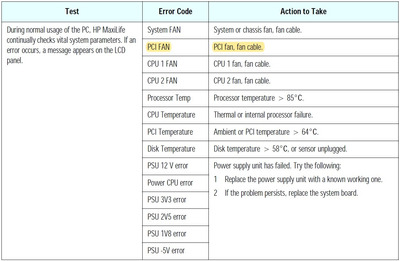
The thing is that when I push the power button, the self test starts showing in the display ( to give you an idea: https://youtu.be/S4MWiJpENu0) but the system does not start. In the display the error code states "No hardware monitoring". 😕
My question then is, could it be the case that the motherboard cannot be used inside another cabinet/chassis other than the original? (maybe the original cabinet has got another cable that must be connected to the motherboard, to accomplish hardware monitoring functions?)

I couldn´t find much information on it but a rather general online manual, nothing specific related to the issue I am experiencing. So I decided to ask for hints in the most suitable online forum for this type of subject.

Any suggestion would be more than appreciated! Thank you very much in advance!

Reply 1 of 31, by kwyjibo

User metadata
Rank Newbie
Rank
Newbie

If I remember correctly the motherboard comes with 3 memory slots. The bottom slot can be used to connect a riser to use sdram memory.

If the riser is not present, a special module must be connected in that module and it is not a regular RDRAM continuity module.

Maybe that is your case?

Reply 2 of 31, by Con 2 botones

User metadata
Rank Member
Rank
Member

Hello there!
Thank you for replying.

You remember correctly. The board comes with 3 RIMM memory slots. RIMM modules have to be installed in pairs, otherwise, if you only install 1 module, you must insert the "continuity module" in one of the slots.

Currently, I have installed a 128MB module in the first memory slot (the one closer to the CPU), the second slot is empty and the third slot is filled with the "continuity module" (I am not sure I am able to upload an image in this forum, I´ll try it later).
Do you believe the problem is related to RAM configuration? In the display mentioned above the RAM test is passed.

Once again, thank you.

Reply 3 of 31, by pentiumspeed

User metadata
Rank l33t
Rank
l33t

Rambus is a daisy-chained through RIMM modules , One goes out from group of contacts then through again daisy-chained through set of chips or just traces on CRIMM then out through another sets of contacts on each RIMM. The RIMM slots has to be filled completely to complete the loop circuit to complete the circuit thorugh RIMM slots with filled modules of any memory or continuity modules from chipset and back to chipset.

So you need either another same speed RIMM module as installed memory RIMM or another continuity RIMM to fill one of empty slot.

Rambus does not care about number of slots or three or could be 5 slots, even 1 slot RIMM (heh) etc.

Cheers, Pentiumspeed.

Great Northern aka Canada.

Reply 4 of 31, by PC Hoarder Patrol

User metadata
Rank l33t
Rank
l33t

In a single processor system you should have a processor terminator card in the CPU2 slot - do you have one?

If you only have single RDRAM RIMM module this should be in slot 0 (nearest the processor slots), a CRIMM (or an equivalent RDRAM RIMM in size / speed to what's in slot 0) in slot 1 and a CTRIMM in slot 2.

CPU-Mem_Config.jpg
Filename
CPU-Mem_Config.jpg
File size
51.76 KiB
Views
2140 views
File license
Fair use/fair dealing exception
CTRIMM.jpg
Filename
CTRIMM.jpg
File size
201.36 KiB
Views
2141 views
File license
Fair use/fair dealing exception

Also, No Hardware Monitoring is classed as a system board problem - maybe inspect closely for damage / component failure - are you getting any beep codes along with the message?

Reply 5 of 31, by kwyjibo

User metadata
Rank Newbie
Rank
Newbie

That what I wanted to point out.

As pointed by PC Hoarder Patrol you need CRIMM p# D8660-63001 (maybe CRIMM's are standard and you can use any "brand") and a terminitaror module (P# 5065-1281) at least to make the memory configuration correct.

In the following link you can find more part numbers to ease your search:

https://web.archive.org/web/20040219220400/ht … 15/lpv06815.pdf

Reply 6 of 31, by Con 2 botones

User metadata
Rank Member
Rank
Member

Thank you very much kwyjibo, pentiumspeed and PC Hoarder Patrol for your feedback!. 😀

You all suspect the issue has to do with RAM configuration. Although I don´t get any beeps (naturally, no beepers/pc speakers present) and the self-test message in the display is ambiguous, I am thinking you are right:

Motherboard + display:

20190826-210456.jpg

20190826-210409.jpg

The only RIMM module is inserted in Slot 0, Slot 1 is empty and Continuity module is placed in Slot 2:

20190826-210519.jpg

Continuity module:

20190826-210648.jpg

As seen in this picture, the second CPU slot has got its terminator in place:

20190826-210528.jpg

There are also some dip switches that I won´t touch until I take a look at the motherboard manual (in case I find it) properly:

20190826-210859.jpg

The "box" with the display and power+reset button:

20190826-210659.jpg

CPU slots:

20190826-210815.jpg

As you can see, there are no bulging capacitors and the board looks well taken care in general.

I will try moving the continuity module next to RAM slot 0, where the only RIMM module is installed, and let you know the results.

Once again, thank you all very much! 😀

Reply 7 of 31, by kwyjibo

User metadata
Rank Newbie
Rank
Newbie

You can also check the Asus manual for the board:

https://www.rom.by/files/ASUS_P3C-D.pdf

In the RIMM possible configurations you can see:

          RIMM0    RIMM1      RIMM2
1 RDRAM RIMM CTRIMM C-RIMM
2 RDRAM RIMM RIMM CTRIMM

Reply 8 of 31, by Con 2 botones

User metadata
Rank Member
Rank
Member

Wow, thank you kwyjibo ! this manual will be most helpful!

Which confuses me a bit is the distinction between the "RDRAM Continuity Module" and the "RDRAM Terminator Module" mentioned in the image below. It seems those are two different things/pieces

RAM-Config.jpg

Ok, according to this image you shared above:

RIMMconf.jpg

it means since I don´t own another RIMM memory module right now, if I moved the "RDRAM Continuity Module" next to the RIMM slot, the third slot (slot 2) would remain empty and still be needing the "RDRAM Terminator Module" (which I don´t own) to be inserted for the system to boot. 😢

Anyway, I think it won´t be difficult to acquire another RIMM module to place in memory slot 1 and leave the "RDRAM Continuity Module" for slot 3 (as also suggested in the chart above). Or am I misinterpreting the chart and I would still need the mentioned "RDRAM Terminator Module" forcefully?

Reply 10 of 31, by Con 2 botones

User metadata
Rank Member
Rank
Member

Hello kwyjibo again.

I managed to buy a couple 800mhz RIMM memory modules and a pair of RDRAM Continuity Modules (just in case). Nevertheless I must confess it is not being easy to find the required "RDRAM Terminator Module".

Do you think it could be possible someday you uploaded a picture of your system (a zoom-in one to the Ram slots)? Maybe there´s an id or serial number so I can try to find it on eBay.

Thank you very much in advance!

Reply 13 of 31, by Intel486dx33

User metadata
Rank l33t
Rank
l33t

I have some Kayak XA’s and XU’s.

If you get the “Happy face” that is a good sign.
Kind of like a Mac boot screen “Happy face”.

Attachments

Reply 14 of 31, by Con 2 botones

User metadata
Rank Member
Rank
Member

Hello and thanks!
I do get the "happy face". Unfortunately I´ve been having difficulties finding a "RDRAM Terminator Module", specially at a reasonable price.
I´m also a bit confused if the "RDRAM Terminator Module" and the "RDRAM Continuity Module" are actually different devices or if the difference is just in the role they play depending on the slot they are placed, so to speak.

According to a web images search, this is a "RDRAM Terminator Module":
https://ibb.co/7KXs4cN

And this is a "RDRAM Continuity Module", which I actually have a couple:
https://ibb.co/YpFwgw3

I suspect the former is the case, since I´ve tried with 2 different "RDRAM Continuity Module" I do own, and no luck.
Are you able to clarify this particular subjetc? Thank you very much in advance!

Last edited by Con 2 botones on 2021-11-25, 20:11. Edited 1 time in total.

Reply 16 of 31, by Con 2 botones

User metadata
Rank Member
Rank
Member
kwyjibo wrote:

I am afraid they are different hardware devices 🙁

Yes...it seems so, I find it frustrating because I´ve seen RIMM based systems that do not need this particular RDRAM Terminator Module, they are happy with just the Continuity modules.
Thank you!

Last edited by Con 2 botones on 2021-11-25, 20:15. Edited 1 time in total.

Reply 17 of 31, by Con 2 botones

User metadata
Rank Member
Rank
Member

Ok, I managed to acquire the (in)famous RDRAM Terminator Module for this system on eBay.

Now I get all happy faces (RAM, CPU, etc) through diagnosis, but one, stating "PCI FAN". What the heck!?

hayak2.jpg

hayak.jpg

I´m out of patience with this board, if somebody wants it I am willing to donate it.

Reply 18 of 31, by pentiumspeed

User metadata
Rank l33t
Rank
l33t

Sometimes we have to pay lot to get hard to get parts and this is one of these case you have to accept that and get terminator RIMM.

Cheers,

Great Northern aka Canada.

Reply 19 of 31, by PC Hoarder Patrol

User metadata
Rank l33t
Rank
l33t

One of the 3 pin fan headers on the board is designated for the 'PCI Area' - most probably it's either not connected or not in spec.

HP LCD Error Codes.jpg
Filename
HP LCD Error Codes.jpg
File size
125.37 KiB
Views
1697 views
File license
Fair use/fair dealing exception
Filename
xm600__kayak__128_mb_ram (series 1).pdf
File size
2.96 MiB
Downloads
66 downloads
File license
Fair use/fair dealing exception
Last edited by Stiletto on 2020-09-07, 23:12. Edited 4 times in total.