VOGONS


First post, by SSTV2

User metadata
Rank Oldbie
Rank
Oldbie

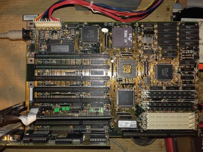
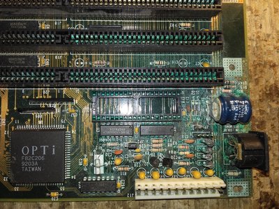
I managed to obtain an original motherboard of the BIOS UV-EPROM chip that I wrote about here: BIOS image collection - requests, discussion etc

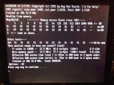
The motherboard seemed badly damaged by a leaky battery at first, but after cleaning the corroded area, it didn't look too bad. Overall, had to patch 8 open traces and replace all contacts in the KB controller's DIP socket. MB succesfully POSTed at the first try. It had badly configured L2 cache at first (different size SRAM ICs and wrong jumper settings), also, 2 SRAM ICs in BANK1 were faulty. Anyway, reconfigured L2 cache and PC loaded command prompt W/O hanging. I was able to bench MB with DOOM and other software properly, cache check showed right ammount L2 being installed.

But after some time, MB started to hang in DOOM timedemos and crash, even when starting a scandisk... Cache check wouldn't pass either, it just kept crashing. Set L2 timings from 0WS (default) to 1WS, cache check would then pass, but DOOM still kept crashing the system. Long story short, it was nor RAM nor cache related, I've noticed one bizzare thing in the CMOS settings:

0s.jpg
Filename
0s.jpg
File size
1.5 MiB
Views
884 views
File license
Fair use/fair dealing exception

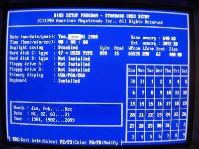
Can you spot what's wrong here? 🤣
Hint -> RTC time keeping clock had stopped working.

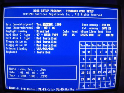
Every time the system crashes, clock increments by one sec:

6s.jpg
Filename
6s.jpg
File size
1.31 MiB
Views
884 views
File license
Fair use/fair dealing exception

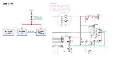
I've inspected the corroded area once more, checked every VIA and trace again, found nothing, except for a bad Q2 transistor, which is a part of a switch that feeds +5V to the RTC clock gen. circuit. Replaced the transistor, clock gen. circuit now receives proper +5V voltage, but clock in the BIOS still doesn't work.

Q2.jpg
Filename
Q2.jpg
File size
1.38 MiB
Views
884 views
File license
Fair use/fair dealing exception

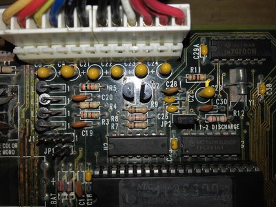
I'll have to dive deeper into the circuit tomorrow, someting's still bad there.

MB.jpg
Filename
MB.jpg
File size
1.9 MiB
Views
884 views
File license
Fair use/fair dealing exception
DMG.jpg
Filename
DMG.jpg
File size
1.86 MiB
Views
884 views
File license
Fair use/fair dealing exception

Could these crashes actually be caused by a non-functioning RTC time keeping and if so, why??? First time dealing with such an issue.

Reply 1 of 13, by Tiido

User metadata
Rank l33t
Rank
l33t

When RTC is stopped it means the 32768Hz crystal isn't oscillating, so I would check the stuff tha tthe crystal is connected to. Chances are that the 82C206 chip is faulty too, which is where the RTC itself lives in but seeing this battery damage, I'm pretty sure the problem in mechanical in nature.

T-04YBSC, a new YMF71x based sound card & Official VOGONS thread about it
Newly made 4MB 60ns 30pin SIMMs ~
mida sa loed ? nagunii aru ei saa 😜

Reply 2 of 13, by feipoa

User metadata
Rank l33t++
Rank
l33t++

In my experience, usually a non-functioning RTC causes a no-POST situation, but I don't want to generalise this. In a board of mine which had a similar level of corrosion destruction, I had to replace the crystal - but the symptoms were different, the clock counting speed non-uniform. My guess the issue is due to a marginal trace connection or joint. When I was testing a 386 motherboard for such issues, when I probed a joint and path with the multi-meter, it beeped (connected), but the pressure from the probe was actually making it connected. Without the pressure from the probe, it was OC. For corrosion like this, I've had some traces which measured through, but after some up-time, the connection was lost. This is especially true for the thinner traces. Also, I've had to desolder DIP components because there was a hidden trace disconnect underneath.

I assume you scrapped off all the corrosion, but apparently the corrosion will return if you don't neutralise it in acetic acid (vinegar).

Plan your life wisely, you'll be dead before you know it.

Reply 3 of 13, by SSTV2

User metadata
Rank Oldbie
Rank
Oldbie

Okay, I've figured out both problems for the clock non ticking in CMOS and constant system crashes. Clock problem was caused by the absence of RTC clock oscillations (obviously), a 10pF cap (C30) next to the quartz resonator had become a 8M resistor, most likely it had soaked in alkaline electrolyte through the leg cracks.

The constant crashing problem was caused by a open "POWER GOOD" trace... I had it repaired the 1st time, but somehow missed a weak spot in it, just behind a KB connector (two black specks can be seen), so that trace had reopened and all hell broke loose 😠

It lives now, installed 128KB of L2 (BANK0 4x 32Kx8)

1.jpg
Filename
1.jpg
File size
1.17 MiB
Views
806 views
File license
Fair use/fair dealing exception

Glad that 82C206 is OK at least. I did neutralise the alkali, but I'll have to repeat the whole etching/cleaning process just to make a nicer finish (it was only the 1st pass of cleaning so that the damage could be evaluated).

Reply 4 of 13, by Tiido

User metadata
Rank l33t
Rank
l33t

Very nice, congrats ~

T-04YBSC, a new YMF71x based sound card & Official VOGONS thread about it
Newly made 4MB 60ns 30pin SIMMs ~
mida sa loed ? nagunii aru ei saa 😜

Reply 5 of 13, by pentiumspeed

User metadata
Rank l33t
Rank
l33t

Repair story:

I had a so called computer buried in a (long ago) proprietary case for automotive service manual look up computer built around a AT pentium motherboard and cannot be rebuilt into new, as it has security lock for the software (readable from optical discs (standard) integrated in part of chassis. Power supply is also proprietary too. Let focus on power supply:

Computer was rebooting at random and soon traced to the power good powered from one of voltage output from supply, small daughter-board mounted on the exterior of the power supply (!!). A online search on this IC revealed it is a delayed timing chip (few pins) using capacitor as timing. The yellow small capacitor was bad, when I removed, the capacitor's leg came out easily.

Done. A perfect working computer.

Cheers, Pentiumspeed

Great Northern aka Canada.

Reply 6 of 13, by feipoa

User metadata
Rank l33t++
Rank
l33t++

Nice work. Sounds like your board had similar issues as mine after battery leak damage. Like you, I also replaced the ceramic capacitor near the 32K crystal (and the crystal) and had a faulty repaired trace.

I should have posted this earlier: Date/Time in BIOS counting slowly (seconds)

The trace repair job on this board is a mess and its on my list to redo it. Around 18 traces were severed. This is one of the more desirable true 386 boards, so it would be worth it to patch it more neatly. Last I looked at the board (18 months ago?) some blue corrosion had returned.

Plan your life wisely, you'll be dead before you know it.

Reply 7 of 13, by SSTV2

User metadata
Rank Oldbie
Rank
Oldbie

Thanks, it was easy to figure out why the clock wasn't ticking, but it made no sense to me that it could cause such system instability. I had C30 replaced with a 27pF cap at first (27pF is used in most systems, IBM 5170 used it originally too), but it caused clock to tick 2 or 3 times slower than it should, kind of strange, considering that RTC clock gen. circuit used in that MB is identical to that of the 5170, crystal resonator might also be slightly off the specs.

Here's a clock gen./battery circuit from a 5170, hosted at -0°:

5170_battery_circuitry.jpg
Filename
5170_battery_circuitry.jpg
File size
256.43 KiB
Views
741 views
File license
Fair use/fair dealing exception
pentiumspeed wrote:

Computer was rebooting at random and soon traced to the power good powered from one of voltage output from supply, small daughter-board mounted on the exterior of the power supply (!!).

I would have never suspected a PG signal to be the culprit here as the absence of PG should result in the CPU being halted, because when PG is low, reset signal should be asserted until PG goes high (the whole idea behind PG), while I still had a functioning system, sometimes could even finish the whole DOOM timedemo. Absent PG can be crudely worked around by connecting a +5V line directly to it.

feipoa wrote:

it would be worth it to patch it more neatly

Your MB is half bad, if you'd follow the same method of trace patching as I did, then the end result should look near perfect. Use donor PCB, scrape off solder mask of a selected trace, tin and peel it off. Turn it over when soldering, so that the matte side sticks out, matte side doesn't stick to the soldering iron easily which makes patching traces a breeze.

By the way Tiido, you had mentioned in one of the threads, that you were able to OC ISA bus to 16MHz, basically doubling the default freq., could you post the DOOM timedemo (min. settings) results from a Phil's DOS bench suite, using that system? I'm getting around 3200-3300 realtics with a WD90C30 VGA, 0WS L2 and a 33MHz CPU.

Reply 8 of 13, by Tiido

User metadata
Rank l33t
Rank
l33t

What are the "min. settings" and which demo ?

40MHz 486DLC, 32MB RAM (tightest timings), 128KB write-back cache (tightest timing), WD90C30 video, 16MHz ISA
No sound, Low detail, full screen (with all statusbar visible) gives 5026/9473 for demo1, 3836/7115 for demo2, 2134/4119 for demo3.

T-04YBSC, a new YMF71x based sound card & Official VOGONS thread about it
Newly made 4MB 60ns 30pin SIMMs ~
mida sa loed ? nagunii aru ei saa 😜

Reply 9 of 13, by SSTV2

User metadata
Rank Oldbie
Rank
Oldbie
Tiido wrote:

What are the "min. settings" and which demo ?

I meant lowest possible details option for DOOM in Phil's DOS bench pack, it runs a timedemo3 with 2134 realtics. Wow, your system was able to score 18FPS in demo3 with low graphics details and a full screen. I bet the FPS in DOOM increased by about 4 FPS on average after OCing the ISA bus, right?

Reply 10 of 13, by Tiido

User metadata
Rank l33t
Rank
l33t

Not quite 4, at 8MHz demo3 with same settings got 4801, ~15.55FPS, vs ~17.78, but still a substantial increase.
At smallest image size 8MHz got 1994 (~37.45FPS), 16MHz got 1810 (~41.26FPS), so almost 4 FPS extra 🤣

T-04YBSC, a new YMF71x based sound card & Official VOGONS thread about it
Newly made 4MB 60ns 30pin SIMMs ~
mida sa loed ? nagunii aru ei saa 😜

Reply 12 of 13, by feipoa

User metadata
Rank l33t++
Rank
l33t++

10 MHz is considered a safe upper limit for most cards. Due to the fixed divisors, on some systems you get either 8.3 Mhz or 11.1 MHz to the ISA bus, depending on the FSB. I'd consider 11.1 MHz only after extensive testing. 16 MHz - do you get HDD write errors? I wonder how long Windows would last.

Plan your life wisely, you'll be dead before you know it.

Reply 13 of 13, by Tiido

User metadata
Rank l33t
Rank
l33t

I had to cherry pick a HDD, there's a "modern" 40GB Seagate drive in the machine. Older stuff will not work at all or actually does get corruption happen. I am only using WfF 3.11 on it, it seems to run without trouble but I am not really doing anything more interesting than accessing network shares on it and occasionally mucking around with hardware.
11MHz and 12.5MHz works fine on all the hardware I have, I have nothing where ISA is under 8MHz except for PIII era things where you're not given an option in BIOS but it doesn't really matter there either, since only sound cards are ever in those ISA slots.

T-04YBSC, a new YMF71x based sound card & Official VOGONS thread about it
Newly made 4MB 60ns 30pin SIMMs ~
mida sa loed ? nagunii aru ei saa 😜