VOGONS


First post, by feipoa

User metadata
Rank l33t++
Rank
l33t++

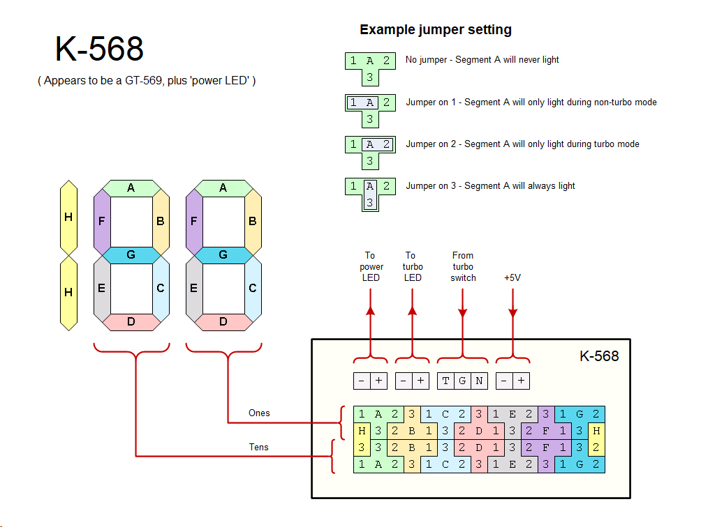
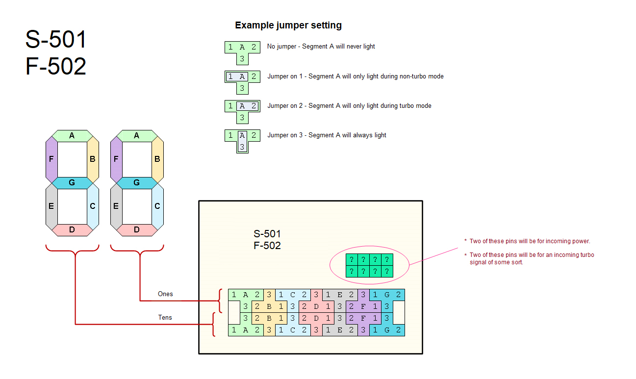
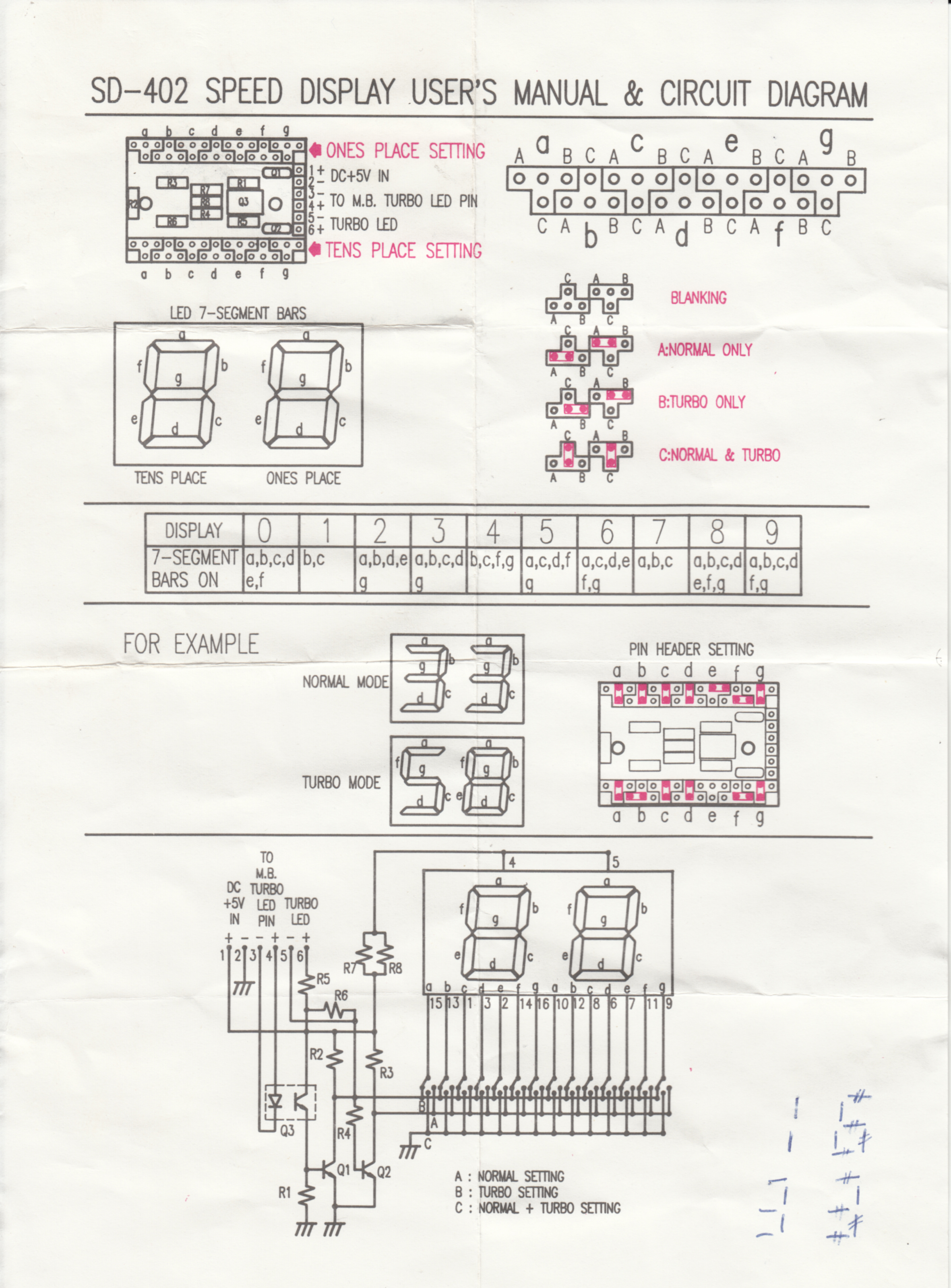
I have the diagrams for a 2-segment +1 LED MHz display and I tried to follow but the result is way off. I had no trouble setting up my 2+1 segment MHz displays with this jumper sheet, but this display from my 386 case is giving me trouble. It is normally set for 20/40 MHz, but I want to set it to 33/66 MHz. Does anyone have the jumper sheet for this particular MHz display? There are three transistors on the PCB.

At power on, the LED display has the smarts to know the system is not in Turbo mode yet, even if you have the Turbo button pressed. So at boot up, it will display the lower MHz value, regardless of whether Turbo is pressed. And Turbo light remains off. Once the system has passed POST, the the turbo light should go on and change the MHz display to whatever Turbo value you set. So the turbo switch actually goes to the motherboard and there is a single wire that comes from the motherboard which enacts this sort of over-ride of turbo, that is, until the system has POSTed. My other MHz displays don't work like this and are more simple. The 386 display is unique in this sense and I was wondering if 33/66 is even possible with this MHz PCB. I can get the LED to display 66 MHz at turbo using random jumper swaps, but de-turbo remains garbled.

Anyone with a proper jumper sheet? Would be much appreciated.

386_MHz_Display_LED_disagrees_with_setup_sheet.jpg
Filename
386_MHz_Display_LED_disagrees_with_setup_sheet.jpg
File size
1.89 MiB
Views
1164 views
File license
Fair use/fair dealing exception
386_MHz_Display_Jumpers.jpg
Filename
386_MHz_Display_Jumpers.jpg
File size
1.06 MiB
Views
1164 views
File license
Fair use/fair dealing exception
386_MHz_Display_Front.jpg
Filename
386_MHz_Display_Front.jpg
File size
333.85 KiB
Views
1164 views
File license
Fair use/fair dealing exception

Plan your life wisely, you'll be dead before you know it.

Reply 1 of 9, by feipoa

User metadata
Rank l33t++
Rank
l33t++

There is a collection of MHz display diagrams here, http://www.minuszerodegrees.net/led_speed_dis … eed_display.htm , though I don't see my particular unit, which has number 86887. Ther'es also SB-010B written on the PCB. The diagram I show in the background of my photo works for 20/40 MHz, but not 33/66 MHz.

There are probably the more intuitive diagrams
http://www.minuszerodegrees.net/led_speed_dis … 20-%20K-568.jpg
http://www.minuszerodegrees.net/led_speed_dis … 20-%20S-501.jpg

And here's a schematic which has 3 transistors in it:
http://www.minuszerodegrees.net/led_speed_dis … 0-%20SD-402.jpg

Plan your life wisely, you'll be dead before you know it.

Reply 2 of 9, by feipoa

User metadata
Rank l33t++
Rank
l33t++

With both the dummy diagram (background photo of mine) and the more intuitive chart (link above), I get the same result: A3, B1, C3, D3, E2, F2, G3 x 2 for 33/66 MHz. The jumper block headers must have some non-conventional numbering.

Plan your life wisely, you'll be dead before you know it.

Reply 3 of 9, by Tiido

User metadata
Rank l33t
Rank
l33t
jumpers.jpg
Filename
jumpers.jpg
File size
334.82 KiB
Views
1127 views
File license
Fair use/fair dealing exception

That's how almost all the displays work. Red and blue depend on turbo switch position, green is always lit segment.

T-04YBSC, a new YMF71x based sound card & Official VOGONS thread about it
Newly made 4MB 60ns 30pin SIMMs ~
mida sa loed ? nagunii aru ei saa 😜

Reply 4 of 9, by feipoa

User metadata
Rank l33t++
Rank
l33t++

Thanks, yes, I just realised after I posted my comment that my PCB probably has the the segments inverted from this drawing: http://www.minuszerodegrees.net/led_speed_dis … 20-%20S-501.jpg - that is, due to where the missing header pin is. Let me play with this some.

Plan your life wisely, you'll be dead before you know it.

Reply 5 of 9, by feipoa

User metadata
Rank l33t++
Rank
l33t++

OK, so the issue was 1) that ones and tens rows were inverted from the drawing, but also, 2) that some of the headers were heavily oxidised and weren't making contact. I cleaned the pins and the issue has now been resolved.

Plan your life wisely, you'll be dead before you know it.

Reply 6 of 9, by feipoa

User metadata
Rank l33t++
Rank
l33t++

One of the segments on the above photographed MHz display has died. I made sure there wasn't a corroded jumper issue by desoldering the display itself and hooking each segment up manually to a power supply w/resistor. This particular unit is 20.2 mm x 16 mm x 7 mm and is smaller than most computer tower displays, perhaps because it fits into a 3.5" bay cover. Finding a common anode replacement LED in yellow had proven difficult , however after using digikey's filter engine to grab non-stock part numbers and plugging them into mouser, I've come up with DA04-11YWA. Only 16 in stock. https://www.mouser.ca/ProductDetail/Kingbrigh … ir1QXpU9w%3D%3D

After ordering a replacement, I decided to try a dirty trick to fix the LED display. I put the display in the freezer for about 90 minutes, took it out, and hooked a variable DC power supply w/91-ohm resistor up to the problematic segment. The broken segment turned on, but did not stay lit. Moving the jumper wire around, segment still not lighting back up. I then cranked the voltage way up on the power supply, probably in the teens or early 20-something volts. I did not look at the PSU because I was looking at the segment. While cranking up the voltage, I noticed the segment go from yellow, to bright yellow, then to orange. Once the orange was starting to dim, I took the voltage down to 0 volts, then back up to 4 volts. I then let it sit at 4 V for 10 minutes. I removed power, and tested it again in 20 minutes. Still working.

The bad segment is fixed for now, but for how long, we'll see.... Anyone else try something similar to fix their MHz display? I first tried heating the lead with an iron, but that didn't work, so I went the opposite direction and froze it.

Plan your life wisely, you'll be dead before you know it.

Reply 7 of 9, by TheMobRules

User metadata
Rank Oldbie
Rank
Oldbie

I have a turbo module with the same "smaller than usual" 2 digit MHz display, with several dead segments. Coincidentally, a few weeks ago I also ended up acquiring the exact same Kingbright part you ordered! It was the only one I found that matched the size, pinout and common anode type of display. I haven't had time to solder it to the PCB yet.

However, I have already desoldered the broken display so I may try your fix on that one. One difference I noticed is that my PCB has one resistor for each segment in the display to limit the current, not sure if that's better or worse than most which use a single resistor. In my case the display was installed in a case with a power supply that had blown caps and voltages were totally out of spec, so I assume that may have played a part in the display having dead segments, but obviously also these things die at some point after heavy usage.

Reply 8 of 9, by feipoa

User metadata
Rank l33t++
Rank
l33t++

Really tough finding this form factor. I ultimately ordered two. I suspect it will be non-stock when liquidated.

When testing your LED removed from the PCB, keep in mind that your multi-meter's diode test setting is unable to find the segments. I had a tough time finding which pins were the common anode, but they are pins 4 and 5. You can trace where the 5V jumper on the PCB goes to which pin on the MHz display to locate the common anode pins.

Were LED's in computer cases almost always common anode, or were some common cathode?

The segment is still lighting up, so I'm going to gamble that it is fixed and solder it back onto the PCB.

EDIT: I have soldered it back to the PCB and re-positioned the jumpers. The fixed segment is about 5% dimmer than the others. No big deal to me. I should point out that before I put the LED display in the freezer, I tried taking the broken segment up to 30 V and it didn't help. The combination of a frozen LED display and 20-ish volts for 1-2 seconds is what fixed it. Also, you need not desolder the LED display from the PCB. You should be able to remove all the jumpers on the PCB and just wire up the broken segment direct to the LED's pins.

Plan your life wisely, you'll be dead before you know it.

Reply 9 of 9, by feipoa

User metadata
Rank l33t++
Rank
l33t++

My order of DA04-11YWA has arrived. Be warned, although it is classified as "yellow", it looks like a solid orange to me. I wonder what their actual "orange" looks like. Here is what the yellow looks like. It looks a lot orange in person.

2-digit_small.JPG
Filename
2-digit_small.JPG
File size
48.39 KiB
Views
718 views
File license
CC-BY-4.0

It is definitely the green LED that is needed: DA04-11GWA, for which mouser is out of stock. Using a common cathode instead of a common anode and reversing polarity would normally work if your PCB doesn't contain a bunch of transistors, like mine does.

One other issue I see with these Kingbright LED segmented displays is that in the off state, the outline of the segments is too contrasted to the background grey. Here is an example with the slightly larger form factor. If you don't have some kind of screen over the LED display, the segments when off are way too pronounced.

2-digit_large.JPG
Filename
2-digit_large.JPG
File size
49.44 KiB
Views
718 views
File license
CC-BY-4.0

You can see in this image why I wanted to order a replacement for this LED display - there is a chip in the upper right corner, but the Kingbright replacement, both with the ultra contrasted segments and the larger digits may, in fact, look worse than just keeping the display with the chip in it.

Plan your life wisely, you'll be dead before you know it.