VOGONS


First post, by SSTV2

User metadata
Rank Oldbie
Rank
Oldbie

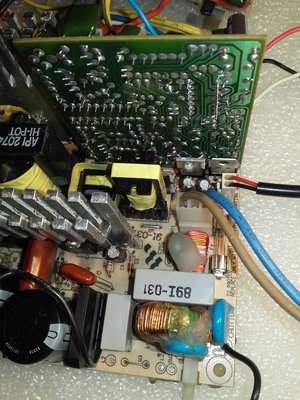
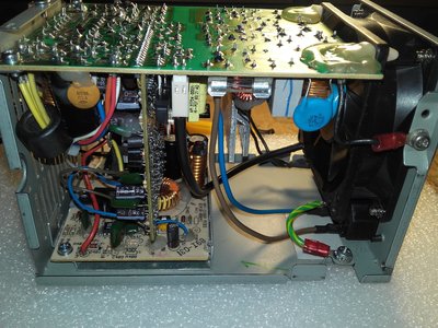
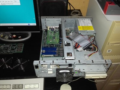
I've set a goal to restore a dead PSU from an IBM 330 series PC. PSU blew up about 15 years ago and I kept its guts in the attic this whole time, knowing that it would be hard to get such PSU in the future. Somehow I've resisted the urge to salvage it for parts all these years.

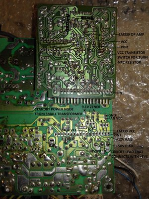
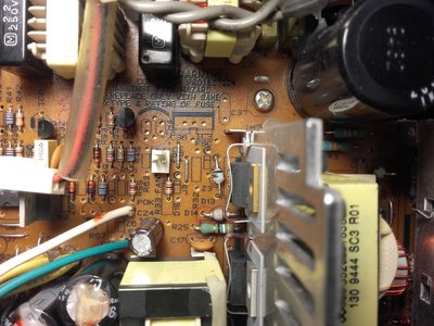
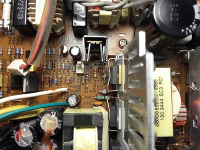
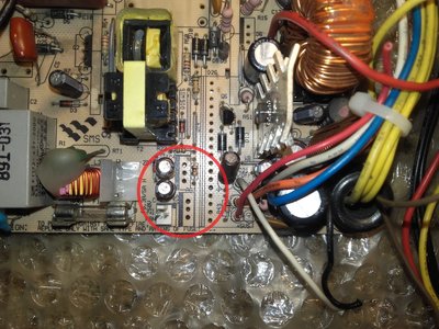
After thoroughly inspecting it, I found bunch of faulty parts, two of which were replaced by me at some point and now it makes me doubt that those were the correct ones. In place of IC4 there was a transistor in TO-220 package and in place of IC5 - a 7805 voltage regulator. I think that both IC4 and IC5 were supposed to be 78xx series voltage regulators, but I'm not 100% certain about that, thus I need that somebody would report correct part numbers, before I place an order for all of them.

2.jpg
Filename
2.jpg
File size
1.42 MiB
Views
920 views
File license
Fair use/fair dealing exception

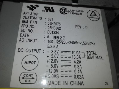
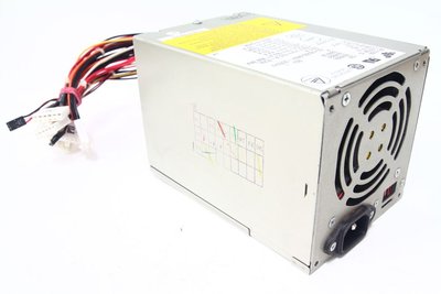
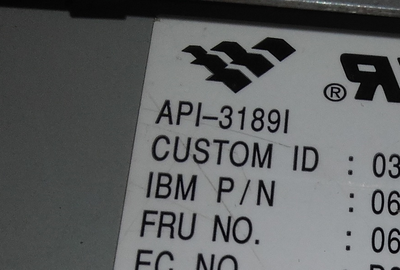
The PSU was made by ACBEL, model - API-3189I, it was used in many models of IBM 330/350 series.

1.jpg
Filename
1.jpg
File size
957.45 KiB
Views
920 views
File license
Fair use/fair dealing exception
3.jpg
Filename
3.jpg
File size
68.23 KiB
Views
920 views
File license
Fair use/fair dealing exception

Reply 1 of 15, by Mister Xiado

User metadata
Rank Member
Rank
Member

Without a schematic, it would be rather difficult to determine the necessary values. I'm over a decade out of practice with my EE skills, rusting away as they are, but my experience with regulators says that there isn't too much wiggle room with them. Without knowing the expected output voltage, it's hard to venture a guess as to what should go there.

b_ldnt2.gif - Where it's always 1995.
Icons, wallpapers, and typical Oldternet nonsense.

Reply 2 of 15, by SSTV2

User metadata
Rank Oldbie
Rank
Oldbie
Mister Xiado wrote:

Without a schematic, it would be rather difficult to determine the necessary values.

True, I tried my best to find a schematic for this PSU, scanned through lots of different AT/ATX schematics, but none were close in design to it.

I did some reverse engineering of this PSU and it looks like that 78xx voltage regulators no way can be fitted in the place of IC4 and IC5. IC5 must be responsible for driving fan and RPM control, because module that connects directly to the IC5, has a NTC resistor in the circuit. I can only think of LM317 voltage regulator, that would be pin compatible with the IC5 trace layout. LM317 pinout: 1 - ADJ, 2 - OUT 3 - IN, makes sense, right?

Now I'm not sure what kind of "IC" should be in the place of IC4, I don't know any pin compatible voltage regulator, that would correspond to the trace layout of a IC4. It's only obvious that "pin1" is a control pin. Output voltage of IC4 should be +5V, according to the "+5VS" silkscreen marking on the PCB and this voltage must feed LM339 OP-AMP at all times. It's basically a standby voltage, when power switch is toggled, this "SB" voltage activates one of the OP-AMPs outputs, which then in turn enables transistor, responsible for switching on TL494 PWM IC, to conduct current.

Somebody, please attach an inside photo of this PSU, I might be missing some fastening parts too 😵

4.jpg
Filename
4.jpg
File size
1.96 MiB
Views
861 views
File license
Fair use/fair dealing exception

Reply 4 of 15, by SSTV2

User metadata
Rank Oldbie
Rank
Oldbie

The last symbol in the model number is an uppercase letter i, though it's easy to confuse it for 1, when a string of numbers is in front of it.

i.png
Filename
i.png
File size
596.48 KiB
Views
829 views
File license
Fair use/fair dealing exception

Reply 5 of 15, by quicknick

User metadata
Rank Oldbie
Rank
Oldbie
SSTV2 wrote:

I did some reverse engineering of this PSU and it looks like that 78xx voltage regulators no way can be fitted in the place of IC4 and IC5. IC5 must be responsible for driving fan and RPM control, because module that connects directly to the IC5, has a NTC resistor in the circuit. I can only think of LM317 voltage regulator, that would be pin compatible with the IC5 trace layout. LM317 pinout: 1 - ADJ, 2 - OUT 3 - IN, makes sense, right?

One of my AT power supplies (Astec SA145) uses an 7805 in the fan control circuit, schematics here.

Reply 6 of 15, by SSTV2

User metadata
Rank Oldbie
Rank
Oldbie

Thanks for the schematics! I have an Astec PSU (SA145-3435) with an exact PCB layout, except mine lacks a fan speed control circuit.

sa145-3435.jpg
Filename
sa145-3435.jpg
File size
953.78 KiB
Views
775 views
File license
Fair use/fair dealing exception

It's a pretty clever and cheap way to adjust fan speed, using a 7805 voltage regulator. Essentialy, they created an adjustible negative voltage reference to 7805's ground pin, using a -12V rail, though API PSU uses a different approach to control fan's speed.

I had removed the top cover of API PSU today and found a drawn in pencil diagram of the PSU's PCB layout underneath it,that I'd left there myself... Funny isn't it? Diagram had marked original parts, that were supposed to be in the place of IC4 and IC5, so IC5 is a LM317T adjustable voltage regulator and IC4 - a TIP31B NPN transistor. I had expected some fancy 3-pin IC in the place of IC4, but apparently it's just a simple BJT.

Reply 7 of 15, by quicknick

User metadata
Rank Oldbie
Rank
Oldbie

Glad it's useful! My Astec also lacks fan speed control, but for a very different reason. Got it for almost nothing at the fleamarket in the early 2000's, it had the +5V rectifier shorted. Replaced that, but I also removed all the parts related to fan control to use them in another project that was never finalized and the parts got lost. And not knowing thermistor's value, I decided to leave it as is, fan connected to +12V.
BTW, take care of those RIFA caps inside, they are a timebomb and will make your PSU into a smelly mess... (link)

Reply 8 of 15, by SSTV2

User metadata
Rank Oldbie
Rank
Oldbie
quicknick wrote:

BTW, take care of those RIFA caps inside, they are a timebomb and will make your PSU into a smelly mess...

Thanks for pointing that out. I had inspected those, encased in the see-through epoxy, capacitors and one of them had micro-cracks on the side. This Astec PSU is pretty well built and all of the main el. caps are still good, but I'm not using it in any system at this moment, its case just doesn't look too well with scratches and white specks of zinc coating corrosion all over the surface.

Do you happen to remember where the NTC was located in that Astec PSU, was it mounted on the heatsink of dual rectifier diodes or was it just dangling in the air? I might just recreate the fan speed regulation circuit in it, while I'm working on the API PSU restoration 😀

Reply 9 of 15, by Miphee

User metadata
Rank Oldbie
Rank
Oldbie
SSTV2 wrote:

The last symbol in the model number is an uppercase letter i, though it's easy to confuse it for 1, when a string of numbers is in front of it.

Indeed, many sources in Google mention it as API-31891 instead of API-3189I.

Reply 10 of 15, by quicknick

User metadata
Rank Oldbie
Rank
Oldbie
SSTV2 wrote:

Do you happen to remember where the NTC was located in that Astec PSU, was it mounted on the heatsink of dual rectifier diodes or was it just dangling in the air? I might just recreate the fan speed regulation circuit in it, while I'm working on the API PSU restoration 😀

From the little I remember, the thermistor was the "green blob" type, mounted on that heatsink with some white gunk resembling silicone (but harder).

Reply 11 of 15, by SSTV2

User metadata
Rank Oldbie
Rank
Oldbie
quicknick wrote:

mounted on that heatsink with some white gunk resembling silicone (but harder)

Glued to the heatsink using ceramic-based silicone thermal glue, roger that.

I did the simulation of the Astec's fan speed control circuit and using this datasheet, had determined optimal NTC thermistor values, that could be used in it.

Here is shown a voltage drop across the fan at different temperatures, using 330R and 470R NTCs. Original circuit, except a more common 7.5V zener diode is used:

330R: ~15C - 8.2V, ~30C - 10V, ~40C - 12V;
470R: ~15C - 7.6V, ~40C - 10V, ~55C - 12V.

I've already ordered all the parts required, but provider didn't have 330R or 470R NTC thermistors in stock, so I chose a 1k NTC instead. Because of a much higher resistance of it, the negative voltage drop across the ground pin of 7805 reg. had to be reduced, by increasing R32 resistor's value, else fan would reach its max RPM only at ~70C 🤣

R32 is replaced with a 470R resistor instead of 220R. Modded circuit results in such temp. response, using 1k NTC:

~15C - 8.6V, ~30C - 10V, ~45C - 12V.

Reply 12 of 15, by SSTV2

User metadata
Rank Oldbie
Rank
Oldbie

Fixed the API PSU, all voltage rails are in specs and stable, except the -5V rail, which has a faulty 7905 voltage regulator. Instead of -5V it outputs -6.5V now. What a weird type of failure, instead of shorting or being open, it had shifted its stabilising voltage down. Also, base drive transformer (leftmost) emits a buzzing noise at mains frequency, maybe dipping it into varnish would fix that?

5.jpg
Filename
5.jpg
File size
1.39 MiB
Views
641 views
File license
Fair use/fair dealing exception

Reply 13 of 15, by quicknick

User metadata
Rank Oldbie
Rank
Oldbie

Maybe there is too much mains ripple / primary capacitors dried out?
Regarding the 7905, weird and unwanted indeed.
There was a thread recently about a PSU that destroyed a motherboard because of +5Vsb meltdown, and I was thinking of some sort of protection module, maybe a crowbar circuit could be useful in preventing such mishaps...

Reply 14 of 15, by SSTV2

User metadata
Rank Oldbie
Rank
Oldbie

That transformer connects directly to mains through a high voltage film capacitor and later with a main transformer, which actually generates the standby voltage (10V DC output). When PSU is on, the buzzing stops completely, small transfomer buzzes only when PSU is plugged into AC outlet. I think its windings or core got lose over the years of use or knocking around without the case. ATX PSUs have a transistor-based, self oscillating circuit built in, to drive a SB transformer, but this PSU uses main transformer as a passive one?

quicknick wrote:

There was a thread recently about a PSU that destroyed a motherboard because of +5Vsb meltdown, and I was thinking of some sort of protection module, maybe a crowbar circuit could be useful in preventing such mishaps...

Saw that thread, I'd not recommend to alter SB circuit of any type of SMPS, best way to prevent such mishaps, in my opinion, is just to unplug the PSU from the mains.

Reply 15 of 15, by SSTV2

User metadata
Rank Oldbie
Rank
Oldbie

I've finished restoring the PSU, it's back in business now 😎

6.jpg
Filename
6.jpg
File size
1.42 MiB
Views
610 views
File license
Fair use/fair dealing exception

Added a fan control circuit for the Astec:

7.jpg
Filename
7.jpg
File size
1.28 MiB
Views
610 views
File license
Fair use/fair dealing exception

I had abused this PC a lot in the past.

8.jpg
Filename
8.jpg
File size
1.03 MiB
Views
610 views
File license
Fair use/fair dealing exception

Correction for the 3rd post - in order to turn on this PSU, "ON/OFF" wire must connect with ground.