VOGONS


First post, by CuPid

User metadata
Rank Member
Rank
Member

hello,
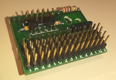
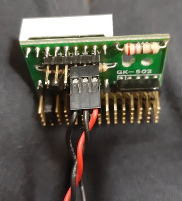
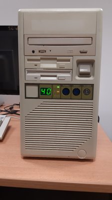
I recently got a very nice AT case with a 2 digit LED display. The small PCB gets three inputs : +5V (and ground), the turbo light, and a single wire for the turbo light status (that plugs to the mainboard). It worked for a while, but after I tried to change the setting, it stopped working : the LEDs stay unlit, and the turbo light status is not updated with the mainboard information anymore 😵
I made sure that the +5V is well on the wires, and I also checked the display segments with a multimeter (I made the segments lit very lightly by pluggin the anode and the catode with a multimeter), just to make sure that it worked.

But now I'm dry, and I don't know what else I could check to figure out what is wrong 😢

Any suggestion would be very welcome. Thanks in advance !

Attachments

  • 20191104_021849.jpg
    Filename
    20191104_021849.jpg
    File size
    228.67 KiB
    Views
    277 views
    File license
    Fair use/fair dealing exception
  • 20191103_215003.jpg
    Filename
    20191103_215003.jpg
    File size
    151.95 KiB
    Views
    277 views
    File comment
    in order : Turbo status, GRND, +5V.
    File license
    Fair use/fair dealing exception
  • 20191103_142546.jpg
    Filename
    20191103_142546.jpg
    File size
    272.15 KiB
    Views
    277 views
    File comment
    Before it stopped working :(
    File license
    Fair use/fair dealing exception

I need a vacation.

tbmtg3-99.png
zav4kj-99.png

Reply 3 of 3, by sf78

User metadata
Rank Oldbie
Rank
Oldbie
wiretap wrote:

Replace the two voltage regulators on the board. You'll have to remove the 7-segment display to desolder them.

In this case I would just cut the legs and solder replacement parts to stubs. You can add more solder to the PCB part if you want to make sure there's a good connection.