VOGONS


First post, by Miphee

User metadata
Rank Oldbie
Rank
Oldbie

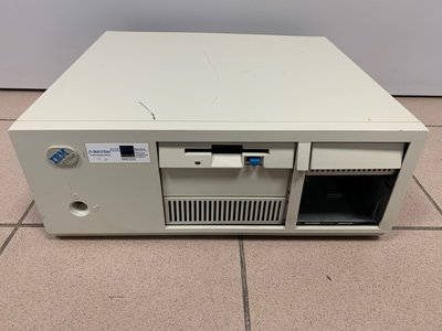
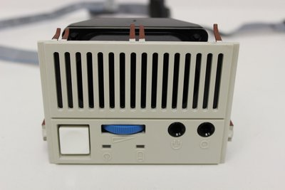
I have an IBM PS/2 57 486SLC2 without a power supply.
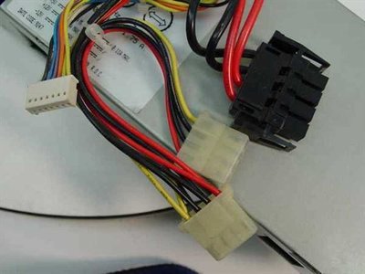
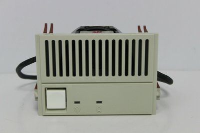
Since a used 79F3443/61G3410 PSU costs more than $100 + shipping I decided to just convert an existing PSU. I identified most pinouts of the original but not all.
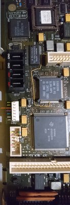
I couldn't reliably identify the

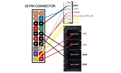
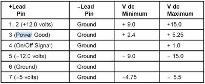
white wire: is it -5V?
orange wire: is it PW_GOOD or +3.3V? I'd go with the first because it's a desktop 486.
purple wire: is it +5VSB? The AT PSUs I know don't have a +5VSB output so I'm puzzled: is this an AT or ATX power supply? Should I just convert an ATX power supply that has the +5VSB output?

Attachments

Reply 1 of 14, by Miphee

User metadata
Rank Oldbie
Rank
Oldbie

Something like this?

Attachments

  • atx-pinouts.jpg
    Filename
    atx-pinouts.jpg
    File size
    252.28 KiB
    Views
    851 views
    File comment
    ATX-IBM
    File license
    Fair use/fair dealing exception

Reply 2 of 14, by SSTV2

User metadata
Rank Oldbie
Rank
Oldbie

You can figure out an exact voltage rail wiring on any motherboard by checking continuity between a bus connector and the PS header of interest. There should be typical +5/12, -5/12 voltage rails, a +5V_SB might exist on that model, at least the IBM PSU, that I restored recently, had it.

Reply 3 of 14, by Miphee

User metadata
Rank Oldbie
Rank
Oldbie

I did that but the MCA bus doesn't have -5V. The same goes for the PW_GOOD and the +5VSB pins.
http://www.interfacebus.com/IBM_MCA_PinOut.html

Reply 4 of 14, by Miphee

User metadata
Rank Oldbie
Rank
Oldbie

Got this picture. Is the ON/OFF signal identical to the PS_ON signal of ATX?

Attachments

  • P2_con.JPG
    Filename
    P2_con.JPG
    File size
    27.54 KiB
    Views
    805 views
    File license
    Fair use/fair dealing exception

Reply 5 of 14, by Miphee

User metadata
Rank Oldbie
Rank
Oldbie

Model 33 has the same pinout.

Attachments

  • psuibm.jpg
    Filename
    psuibm.jpg
    File size
    88.54 KiB
    Views
    796 views
    File license
    Fair use/fair dealing exception

Reply 7 of 14, by Miphee

User metadata
Rank Oldbie
Rank
Oldbie

This is where I face the next problem: the computer is missing the power switch assembly.
I also don't know the pinout of header J19 to locate where the power button goes. I measured what I could.

Attachments

  • IMG_4507.jpeg
    Filename
    IMG_4507.jpeg
    File size
    71.52 KiB
    Views
    748 views
    File comment
    Missing power switch assembly
    File license
    Fair use/fair dealing exception
  • s-l1600 (1).jpg
    Filename
    s-l1600 (1).jpg
    File size
    123.07 KiB
    Views
    748 views
    File comment
    Power switch assembly
    File license
    Fair use/fair dealing exception
  • DSC_0072.jpg
    Filename
    DSC_0072.jpg
    File size
    1.33 MiB
    Views
    748 views
    File comment
    J19 pinouts
    File license
    Fair use/fair dealing exception
  • 9556_Planar.gif
    Filename
    9556_Planar.gif
    File size
    9.46 KiB
    Views
    748 views
    File comment
    J19 header
    File license
    Fair use/fair dealing exception

Reply 8 of 14, by Miphee

User metadata
Rank Oldbie
Rank
Oldbie

Correction, it's probably this switch assembly. I only assume because of the number of pins.

Attachments

  • s-l1600 (4).jpg
    Filename
    s-l1600 (4).jpg
    File size
    120.96 KiB
    Views
    742 views
    File license
    Fair use/fair dealing exception

Reply 9 of 14, by SSTV2

User metadata
Rank Oldbie
Rank
Oldbie

J19 connector is just a front panel header for activity LEDs, power switch and misc. stuff, that can be absent on your model. I think ON/OFF signal pin might directly connect to one of the J19 header pins, but you can bypass J19 for the moment. Connect ATX PSU voltage rails to J18 and J20 connectors accordingly (don't connect anything to the "ON/OFF signal" pin) and try to power it on by shorting PS_ON wire to ground, PC should turn on, unless it has some undervoltage protection circuit on the MB, comprising from OP-AMPs/comparators.

Reply 11 of 14, by Miphee

User metadata
Rank Oldbie
Rank
Oldbie

Alright, it's running now so I'm not going to use the ON/OFF signal pin.
It started with date and time error (00016300) but no options to set it. Any suggestions?

Attachments

  • DSC_0095.JPG
    Filename
    DSC_0095.JPG
    File size
    574.36 KiB
    Views
    694 views
    File comment
    Set date and time error
    File license
    Fair use/fair dealing exception

Reply 13 of 14, by SSTV2

User metadata
Rank Oldbie
Rank
Oldbie

They are, believe me. My first PC was an IBM 8590 XP, imagine having to deal with their technical issues with no prior experience with PCs. Nothing was compatible with the system: PSU, MCA bus, RAM (parity only), cache RAM for HDD (proprietary), floppy drive, hard drive was SCSI and you cound't just swap it for a higher capacity quieter model, because it required a special BIOS setup partition on it, it had 2 sockets for 486 CPUs on a separate CPU board, so on and so on. You could also forget about the sound card option completely.

Reply 14 of 14, by Miphee

User metadata
Rank Oldbie
Rank
Oldbie

All's well that ends well. The 2.88 drive worked fine even though it was super dirty before cleaning.
Since I don't have a 50 pin SCSI HDD it's as far as I go for now.
Believe it or not I love these computers with all the proprietary parts that give me a hard time.
I still have parts missing, like the 212 MB SCSI HDD, the switch assembly, the back cover and all these parts cost an absolute fortune. I'd never spend hundreds of dollars for these, it's highway robbery. MCA sound card? No way for $900 that's crazy. But it's nice to own an IBM machine even if it's not 100% original.
Thank you for all the help. I'll spend more time with it when I get a SCSI HDD.

Attachments

  • DSC_0100.JPG
    Filename
    DSC_0100.JPG
    File size
    1.79 MiB
    Views
    653 views
    File license
    Fair use/fair dealing exception