At the moment, I don't have any pictures of the inside of it yet, as I recently moved, and still have yet to get some screwdrivers moved over. All of this work was done at my local technical school with the aid of my instructor, as I've been attending there for a couple of months now and crazy projects like this one are generally encouraged.
This was all done due to the damaged front panel piece my IBM had when I first got it, as well as the broken front panel locking mechanism that kept it from being able to stay locked shut- here's a picture of that:
I had a few options with the broken corner: I could've molded some clay to it, let it dry off, sanded it smooth, and then painted it over, and when I started at that technical school, I could've even designed and 3D printed a replacement corner piece, however I found that option to be far more complex than I initially realized when I started trying to measure out everything to put it into a 3D model. This is completely ignoring that entire sliding cover, which would've been near impossible to try and recreate and 3D print. I decided to instead go with designing my own front panel, but again, when I started trying to measure it, all the little things that needed to be measured would've made the thing an even more complex option than before.
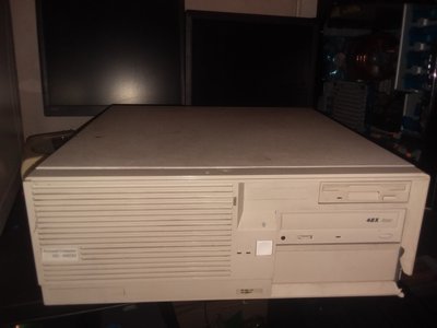
A little while after I was looking into making a new front panel for it and 3D printing it, the instructor brought in his dad's old 486, an old Packard Bell Legend PB400 486SX-25, and gave it to me to work on. When I got inside it, I found that the motherboard had died due to bad capacitors that had leaked and ate through several traces around the integrated video area, and that the old barrel battery had done the same thing, except it was around the power connector, meaning that the thing was basically bricked via being left in an old garage for too long. Despite this, the case itself was in near perfect condition- after cleaning it up a bit, I decided that, because the screw holes on the motherboards lined up with each other, to transfer the IBM motherboard to the case.
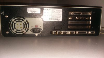
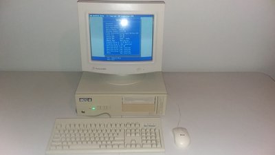
This was far easier said than done. The entire operation took a week, and then some, and required extensive modification of both the case, and the motherboard itself, but I'll get into those once I can get you some pictures of the inside of the thing. Some of you will cringe, and I may receive backlash due to the extensiveness of the modifications, and that a lot of them were more 'destructive,' than 'additive,' but the thing works, just as it did in the old case, and it looks good. Here's some pictures of the outside of the machine, and a view from the back where you can see how the ports sort of lined up. I still need to fashion a little I/O shield for it, and screw in the screw connectors for the VGA, parallel, and serial ports, but other than that, it's in there.
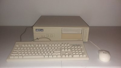
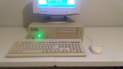
Front of the case, I 3D printed that little badge and painted it black, and then ran a brush with white paint over the letters, the Packard Bell logo used to be there, but I removed it seeing as the motherboard inside it was no longer actually a Packard Bell:
Working on an old computer restoration at school? I wonder what sort of study program allows you to have so much fun at the place of educational institution.
Personally, I'd just patch a missing piece on the front bezel or, at least, would try to find a similar IBM case for the transfer, if finding front bezel would prove too difficult. I understand that this project was meant to practice a certain skill, but I usually tend to avoid hard mods on old hardware at all costs. Looking forward to see how the project turned out.
thats a bummer. yeah same id probably remove that front facia put it on a table and try to mold bondo in around the broken spot, try to sand it down to match and paint it. not much else u can do. if u had the original plastic that broke off you could use some acetone to glue it back together.
Working on an old computer restoration at school? I wonder what sort of study program allows you to have so much fun at the place of educational institution.
Personally, I'd just patch a missing piece on the front bezel or, at least, would try to find a similar IBM case for the transfer, if finding front bezel would prove too difficult. I understand that this project was meant to practice a certain skill, but I usually tend to avoid hard mods on old hardware at all costs. Looking forward to see how the project turned out.
It's just an IT program, basically it allows you to get all the certifications you need (like CompTIA, A+, Greenlee, etc.) to be certified to work in cabling, networking, and computer repair. In this case, I've seen some fairly crazy things done, but I think this takes the cake if you'll pardon my lack of humility. Seeing the modifications now, they all look so simple, but at the time it was hard. I'd say it was one of the most difficult things I've done, and I even had my instructor helping me quite a bit.
As for your comment on modifying the hardware as much as I did, I generally try to avoid it too, though I decided to take a risk here and see what happened- something I likely won't do again unless I have to do so in order to get something to work properly. You can already see a few hints to denote what I've done here, but I took a few close-ups of each mod I ended up doing.
Warlord wrote:
thats a bummer. yeah same id probably remove that front facia put it on a table and try to mold bondo in around the broken spot, try to sand it down to match and paint it. not much else u can do. if u had the original plastic that broke off you could use some acetone to glue it back together.
That's what I had originally planned to do, but the modifications I made make it impossible to get it back into its old case. I'll demonstrate what I've done now that I got a set of screwdrivers today.
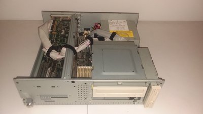
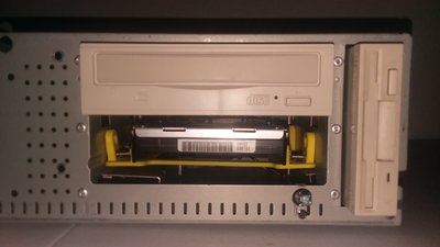
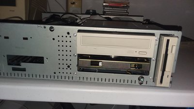
Here's the inside of it. The cable management looks messy, but I've designed it so that all of the wires are either above or pushed away from the PSU's air intake, to provide ample airflow to it.
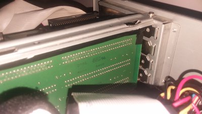
The first, and frankly, the most idiotic, disturbing, and potentially dangerous mod I did was to figure out a way to get the riser card to fit in the shorter case. The riser originally had 5 ISA slots, I think, but it was too tall for the case. I tried the riser that came with the other motherboard, but it didn't work-
So I had my instructor slice off an entire chunk of the top of it with a diamond-tipped tile cutter/grinder.
I did this first to make sure it still worked after that much trauma- and, indeed, it worked! Both the SCSI card and sound card work just fine, which I thought would happen because the riser itself appeared to be electrically dumb, and luckily, it seems I was right. The only reason why I did this is that if it killed the riser card, I could just buy another one (maybe) and forget about continuing the modding process. I sanded it down to make sure the traces were contained in the PCB, and lined the top with three layers of electrical tape to ensure it wouldn't ever short against anything, specifically the steel arm that holds it in place. I had to bend the steel arm a fair bit to get it to grip onto the "new," riser card properly, but it is now solid and you can't wiggle the riser card at all.
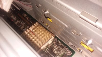
The next problem was that the original 3.5" bay for the HDD was sideways, and mounted to the side of the 5.25" bays- even with the bracket itself unscrewed and removed, there was still a little metal tab that happened to be right over the heatsink on the 486- so with the CPU in the motherboard, it couldn't fit. To fix this, I simply grabbed a pair of plyers, and ripped the heatsink off of the CPU, destroying the ceramic and shattering the die of the CPU, which I subsequently snorted.
Okay, maybe I didn't go that far. Instead, I had my instructor, again, take his grinder to that little metal tab, and it sliced right off. The motherboard now fits in the case with the CPU mounted, but I realized too late that you can't actually remove the CPU while it's in the case- the locking arm is tucked under the 5.25" bays just enough to prevent it from being moved very far. Oh, well, I don't plan on upgrading the CPU anytime soon or removing it for any reason, barring any unforeseen consequences- I mean, unforeseen events.
Two things here- the first is the power button, which looks a bit mangled. This power button was the original that came out of the IBM- the original original power button was just a plastic rod that connected straight into the old power supply, so my instructor drilled the original hole bigger, and drilled two smaller holes to allow the power button to screw into the case. After that, I realized that in order to use the bottom 5.25" bay, I had to knock out the panel that the top screw was screwed into, leaving only the bottom screw. I bent the piece of metal that had been attached to the top of the power button backwards, so it wouldn't get in the way of any installation of drives. I had to snip the original power button to probably 1/8th or maybe even more of its original length before the power button on the case could interact with it properly.
The horrible bent mess that is that 3D printed 5.25" to 3.5" adapter became a necessity once the other 3.5" HDD bay had been removed to allow for the heatsink to fit. The way this 5.25" bay works is unfavorable to say the least, and uses a complex mounting system that was designed by a god-awful human being that had some sort of sick agenda in mind whilst designing it, which is why that bay looks so bent. The connection is very sturdy, however, and neither the HDD nor the 3D printed parts can be moved, even with me tugging on it with a bit of force.
This ugly-as-sin mess was caused by the realization that the PB used a small board that screwed into the case where the LED light indicators and TURBO and RESET buttons are, and that the entire assembly was completely incompatible with the IBM without having issues. During this time, I:
Directly hooked up the LEDs to the IBM motherboard. They were very dim, and every time the HDD indicator would flash, so would the power indicator.
Tried removing those LEDs by ripping them off the circuit board and drilling holes where the leads were, and soldering on the original IBM LEDs to that little PCB to see if it worked. It didn't. It did the same exact thing as before- and I had also ruined the original LEDs in the process. Luckily, the school has tons of the little things, and I soon found a brand-new green LED and a brand new orange LED. I soldered them to the original IBM connector, and I slid them into some heat-shrink tubes, pressed them up against the little lenses that transmit the LED light to the outside of the case, and super-glued it on. It isn't pretty on the inside, but that power indicator light is now a brilliant, bright green. Even in a room with studio lighting, you could probably see that the computer was on. The HDD indicator isn't nearly as bright, which slightly irks me, though it is more than bright enough to see. I'd say it ended up being the same brightness as the original HDD indicator LED was.
I believe that's what all I did to get this thing to do what I wanted to do. I still have a couple of things left, mainly getting a shindig I/O shield set up, and possibly retrobriting that front panel and re-paining the steel shell itself, though that may or may not ever happen, and if it does happen, it'll be a while into the future.
The mod looks pretty nice at the first glance, but you sure have more than just a couple things left to do in order for it to be finished properly and completely. OK, lets start from the beginning.
1. I would've discouraged you from cutting the riser board, but the deed has been done. Riser board slots aren't quite aligned with the case slot grills, which causes cards to lean down when fastened. You need to make four oval holes where the grill-holding rivets are, in order to make its height adjustible. Drill off rivet caps using a larger diameter drill bit than the existing rivet hole in order to remove them, next, drill new holes above each existing rivet hole and connect them using a round file. Secure grills using either rivets or typical case screws. Remove electrical tape from the riser board and apply green solder mask over the exposed traces instead, that tape looks horrible.
2. Case lacks standoffs for the new motherboard. You can easily add robust metal standoffs where they are absent. Get a suitable lenght, double ended M3 standoffs and short threaded M3 countersunk screws. Form 3mm diameter holes for the strandoffs in the case and make them conical (if case sheets are thick enough). Make sure that conical screws are short enough or else screws on the top won't screw all the way in.
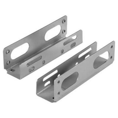
3. That yellow plastic HDD adapter looks awful, use metal adapters as such:
4. I'd suggest using matte LEDs on the front panel instead of transparent. Never use cyanoacrylate to secure something like LEDs on a plastic case parts, that type of glue is brittle, it evaporates and is hard to remove when modifications are required. Instead use hot glue or, ideally, an original PCB with the buttons.
5. I/O shield can be CNC milled from a shiny metal or 3D printed, sanded and spray painted.
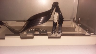
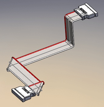
6. SCSI ribbon cable at IDC connector looks stressed. Instead of rolling it up, route cable in the case by folding it at 90 degrees, cable can be wrapped around the fold point to chage directions. Example:
SSTV2 wrote:The mod looks pretty nice at the first glance, but you sure have more than just a couple things left to do in order for it to be […] Show full quote
The mod looks pretty nice at the first glance, but you sure have more than just a couple things left to do in order for it to be finished properly and completely. OK, lets start from the beginning.
1. I would've discouraged you from cutting the riser board, but the deed has been done. Riser board slots aren't quite aligned with the case slot grills, which causes cards to lean down when fastened. You need to make four oval holes where the grill-holding rivets are, in order to make its height adjustible. Drill off rivet caps using a larger diameter drill bit than the existing rivet hole in order to remove them, next, drill new holes above each existing rivet hole and connect them using a round file. Secure grills using either rivets or typical case screws. Remove electrical tape from the riser board and apply green solder mask over the exposed traces instead, that tape looks horrible.
2. Case lacks standoffs for the new motherboard. You can easily add robust metal standoffs where they are absent. Get a suitable lenght, double ended M3 standoffs and short threaded M3 countersunk screws. Form 3mm diameter holes for the strandoffs in the case and make them conical (if case sheets are thick enough). Make sure that conical screws are short enough or else screws on the top won't screw all the way in.
3. That yellow plastic HDD adapter looks awful, use metal adapters as such:
4. I'd suggest using matte LEDs on the front panel instead of transparent. Never use cyanoacrylate to secure something like LEDs on a plastic case parts, that type of glue is brittle, it evaporates and is hard to remove when modifications are required. Instead use hot glue or, ideally, an original PCB with the buttons.
5. I/O shield can be CNC milled from a shiny metal or 3D printed, sanded and spray painted.
6. SCSI ribbon cable at IDC connector looks stressed. Instead of rolling it up, route cable in the case by folding it at 90 degrees, cable can be wrapped around the fold point to chage directions. Example:
In response to 1: The description of that confuses me quite a bit, though I would like to make sure everything's aligned. I understand what you mean by the problem itself, though I'm not sure what you mean with the process of modifying that itself. In regards to the electrical tape issue, I unfortunately am very strapped for money at the moment- the school doesn't have solder mask, just electrical tape and similar things.
2: The motherboard only has that one area lacking a standoff, while all the other mounting points have standoffs and is screwed in at all of them. The missing standoff is also in a low-stress area, where it'll be very rare that I try to change anything or even really touch that area. Those two things combined make me figure that it probably won't hurt anything to leave that unaddressed, but I could be wrong.
3: I agree fully. Once I get some funds that will be one of the first things I'll be buying. At the moment, because it's inside of the case, it doesn't ruin the external look of the build, but a metal set of adapters will look much better and far more professional.
4: I honestly had planned on using hot glue, but for some insane reason, the school has neither hot glue or hot glue guns. I had to make do with what they had, which happened to be some Gorilla Glue my instructor had lying around.
5: I'll 3D print the new I/O shield soon, and likely paint it black to match the back of the case.
6: I'll take it apart and route it differently tomorrow. I didn't know you were supposed to do that with ribbon cables, but I'm glad you told me. That happens to be the only 50-pin SCSI cable I have, so if it gets damaged, that's it- no more fancy 4X SCSI CD-ROM drive.
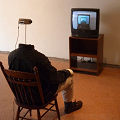
At the moment, the project is going to sort of have to be halted until I can figure out what's going on with my monitor, and if it's bad, until I can get lucky and find another, light(ish) CRT monitor in my area for cheap, or I have to suck it up and save up to cough up the amount of money that getting a similar CRT online will cost me. While I obviously could get an LCD, I'm one of those people that can't deal with using a PC of that age with a crappy Dell monitor from the mid-2000's, which is done often with other PCs of this age. I started this modification process to make the 486 itself look much better, and I'll be damned if I'm going to have spent that much time getting my 486 looking pretty, just for me to stick an LCD monitor on it that likely won't match the color of the case and won't look very good. That's just my own bias showing, I'll be honest there.
I may have messed up, because I got a full steel wrap-around frame that the HDD sits in the center of. 🤣
Jokes aside, it looks massively better than it used to. I don't think words can describe how much better this looks. Same HDD and everything- just installed using a steel frame specifically designed for hard drives rather than that garbage 3D printed muckery. I got this out of a full tower 486 I acquired for free. Had a super high-end 1GB Seagate Decathlon from 1995 in the adapter it came in, but when I tried to format it it just shut off and died. Gave the click of death. I'm actually pretty bummed out about that, because it would've been cool as Hell to have in there. Oh, well. My 541MB drive is enough storage for me at the moment (knock on wood).
I also got a full-size ISA sound card with a true Yamaha OPL chip on it, non plug'n'pray too, so hopefully, it'll work better than the ESS has. Sound card is from 1994, I believe. It's a Crystal 4243. Here's to hoping it works in the first place, and that it does better than the ESS one I had in there prior.