VOGONS


AMD K7 "goldfinger" cloning thread

Topic actions

Reply 160 of 260, by Doornkaat

User metadata
Rank l33t
Rank
l33t
wiretap wrote on 2021-04-05, 19:57:

Nice. Thanks for sharing the mini design. That's a super awesome budget model that should be easy for most people to assemble.

That's much appreciated! 😃
Another plus with this model is the low 3x multiplier. Ever wanted to know how a K7 compares to a Tillamook Pentium MMX? Now you can find out!😅
That and the low profile and not needing external power which may look cleaner in some builds if one cares about those things.

Btw, wiretap, if you're still trying to clone the Northwind GFD I guess they both work the same way, only using different switches (and a resistor on the northwind). If you're interested I can share the schematics that I was able to make from actually having the Innovatek device in my hands and being able to desolder all parts.

Reply 162 of 260, by wiretap

User metadata
Rank Oldbie
Rank
Oldbie

Yea that would be great if you could share them. The Northwind needs a small fix on what we thought was supposed to be a ground pin. 😜

My Github
Circuit Board Repair Manuals

Reply 163 of 260, by snufkin

User metadata
Rank Oldbie
Rank
Oldbie

I wonder if the mini ones might depend on which motherboard they're used with? The short AMD datasheet I could find said that the VID signalling should be TTL levels, which I think means a '1' should be >2v and a '0' should be <0.8V. If I read the gerber right then the mini board can only pull any VID lines to Vcore (so ~1.6ish). Which TTL says is undefined, so one chip may read it as '1' and another as a '0'.

On the upside, if the motherboard VRM does read a 1.6V as a '0', then that sets the Vcore higher than intended, which makes it more likely that the VRM will then read it as a '1' and turn the voltage back down. On the downside, that sounds like it might make for an unstable Vcore.

Similar sort of thing happens with the FID signals to the motherboard as well, although I don't know what those signals are actually used for (some configuration of northbridge perhaps? Or just information for the BIOS?). The actual FID signals to the CPU only need to go to Vcore, so they're all ok.

Reply 164 of 260, by snufkin

User metadata
Rank Oldbie
Rank
Oldbie
gbeirn wrote on 2021-04-05, 21:08:

I am interested in the schematics since I have 20 of those PCBs already and would like to salvage them if possible.

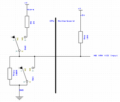
Just looking at the schematic that Wiretap posted on 2021/02/28, what value is being used for R5? It is 2k? I think that effectively means any outputs that need to be switched high are pulled up through a 2k resistor to Vcore. So if, for example, there's a VID being pulled down to GND by a 100 ohm resistor on the CPU PCB, then with a 2k pull-up to Vcore, that output will only go up to ~0.08V, so still be read by the motherboard VRM as a '0'

Similar, but not as bad, for the FID. If they're set to a '0' on the CPU PCB then they're pulled down by a 1k resistor. Which means they'll be pulled up to about 0.6V, so still be read as a '0'.

I'm going to suggest something, but be very careful. I think the idea of that resistor is to act as a current limit in case the dip switches are set wrong, with both sides 'on' at the same time. If they're both set to on, then there's a short between the top and bottom switch. Without R5 then that would short Vcore the GND. Which would be very bad for the motherboard. CPU would probably survive, although traces around the debug header might not.

But, R5 being there, and being 2k, means that the pull up is too weak to overcome the pull downs on the CPU PCB. So, and really BE CAREFUL, try putting a much lower value in for R5. As in just short it out entirely. And make absolutely sure that the dip switches are set right. Doornkaat's version has the benefit that the SPDT dip switch means it's not possible to have both sides on at the same time, so there's no risk.

Really, I think R5 should be a fuse, but it'd need to be a fast acting one. It's possible that what became R5 might have originally been a PTC fuse, but having a quick skim of some specs, the ones with low trip currents tend to have quite a high normal resistance, so might still cause problems with the pull up voltage level.

[just to add... Ah, the possibly obvious solution then is to put the fuse on the ground side instead. So have the Vcore tied directly to the top switch, then have the bottom switch connect to Gnd through a PTC, or maybe a 100 ohm resistor. Haven't thought this through yet mind.]

Last edited by snufkin on 2021-04-05, 23:58. Edited 2 times in total.

Reply 165 of 260, by snufkin

User metadata
Rank Oldbie
Rank
Oldbie

Just to follow up, I thought a diagram showing how I think things are working would help.

Athlon_VID_resistors.png
Filename
Athlon_VID_resistors.png
File size
11.72 KiB
Views
1465 views
File license
CC-BY-4.0

(the switches should really be SPST to match the earlier designs, but weirdly I didn't have a SPST in my library)

This shows how I think the VID lines are wired up. Rcpu may or may not be fitted at the factory, depending on what voltage AMD wanted for the CPU. So for mine VID[1] & VID[2] are fitted, to give 1.6V. Rmb is fitted for all 4 VID lines. So a VID line with no Rmb Rcpu fitted gets pulled up to +5V through a 10k resistor (I measured that on my KA7). If present, then Rcpu is only 100 ohms. That's a much stronger pull down than the 10k pull up, so the VID voltage will end up around 0.05V (5V * 100/(10,000 + 100)). In my case, then with Rcpu fitted for VID[1] and VID[2], and not fitted for VID[0] and VID[3], then my motherboard reads the VID lines as '1001' and outputs 1.6V to the CPU.

The goldfinger devices have to over-ride those pre-set resistors, and get the motherboard to read a '1' or '0' as we want. Pulling down is easy (close SW1 on my sketch) as there's only the 10k pull up on the motherboard to overcome, and there's a good GND supply to the debug header. Pulling up is hard because there might be a 100 ohm pull down to overcome and there's only the Vcore voltage (<2V) to use, unless external power is used.

With that R5 there at 2k, then if SW2 is closed, the voltage at the motherboard VRM VID input hardly moves at all. If R5 is shorted then the VRM VID input becomes the same as Vcore, so probably about 1.6V. That's still not officially high enough to definitely be read as a '1', but may work in most cases. It's closer to a proper '1' (2V) than it is to a '0' (0.8V).

Incidentally, I think the worst case additional current draw (assuming there were never any CPUs factory set to 2.05V) on Vcore caused by the goldfinger with no resistors or external power will be around 50mA, so <0.1W.

[edited to correct Rmb / Rcpu mixup]

Last edited by snufkin on 2021-04-06, 11:40. Edited 1 time in total.

Reply 166 of 260, by Doornkaat

User metadata
Rank l33t
Rank
l33t

Attached schematics for the GFD + tri state switch circuit diagram.
If you need anything else please let me know what and how. I'm a total n00b with those things.

Attachments

Reply 167 of 260, by Doornkaat

User metadata
Rank l33t
Rank
l33t

I have a bunch of Slot A boards I can test the GFD on. I'll get them out of my storage cellar for testing in the next weeks and update this post.

The passive device has so far been sucessfully tested on the following boards:
-Gigabyte GA-7VX Rev. 1.0: multiplier works / CPU VID works
-Asus K7M Rev. 1.04: multiplier works / CPU VID works
-MSI K7 PRO Ver:1: multiplier works / CPU VID works

All tests done with an 800MHz K75 Pluto.

Reply 168 of 260, by snufkin

User metadata
Rank Oldbie
Rank
Oldbie
Doornkaat wrote on 2021-04-06, 09:25:

I have a bunch of Slot A boards I can test the GFD on. I'll get them out of my storage cellar for testing in the next weeks and update this post.

That'd be cool, thanks. I'm probably worrying over nothing, just puts me a bit on edge working out of spec.

All tests done with an 800MHz K75 Pluto.

Is that at 1.7V by default? 0111 on the VID lines? I think that makes it a bit easier for the goldfinger as there's only one line that might possibly need to be pulled high,VID[3], and that's only if you're under-volting.

If I want to push my 1.6V part (Argon 500) from 1.6V to 1.7V then there are 2 VID lines (VID[2..1]) that need to be pulled high, so more chance of one of those lines not being read correctly by the motherboard. Probably doesn't actually matter in my case as the KA7 can set the CPU voltage manually and ignore what the CPU requests.

Reply 169 of 260, by Doornkaat

User metadata
Rank l33t
Rank
l33t
snufkin wrote on 2021-04-06, 12:21:

Is that at 1.7V by default? 0111 on the VID lines? I think that makes it a bit easier for the goldfinger as there's only one line that might possibly need to be pulled high,VID[3], and that's only if you're under-volting.

If I want to push my 1.6V part (Argon 500) from 1.6V to 1.7V then there are 2 VID lines (VID[2..1]) that need to be pulled high, so more chance of one of those lines not being read correctly by the motherboard. Probably doesn't actually matter in my case as the KA7 can set the CPU voltage manually and ignore what the CPU requests.

1.7V default, exactly.
I can check what other CPUs I have.
If I understand your observations correctly setting the 1.6V variants to 1.75V (and possibly 1.7V) should basically be the torture test for passive GFDs, right? (I assume that running any Slot A CPU @1.3V/1.35V isn't going to work anyway.)
I think I have at least one 600MHz Argon and or Pluto somewhere so I could try that as well and include my findings in the previous post.
It'll just take a while for me to find them and crack them open.

Reply 170 of 260, by Doornkaat

User metadata
Rank l33t
Rank
l33t

Oh and also when overvolting only going from 1.6V to 1.7V/1.75V will require more than one low signal being pulled high, right? Meaning in theory going from 1.6V to 1.8V is going to be just as difficult as going from 1.7V to 1.6V, right?

I think I'm starting to understand your analysis. Thanks for that! Really handy for understanding what exactly the GFD does and testing it.

Reply 171 of 260, by snufkin

User metadata
Rank Oldbie
Rank
Oldbie
Doornkaat wrote on 2021-04-06, 12:45:

If I understand your observations correctly setting the 1.6V variants to 1.75V (and possibly 1.7V) should basically be the torture test for passive GFDs, right? (I assume that running any Slot A CPU @1.3V/1.35V isn't going to work anyway.)
I think I have at least one 600MHz Argon and or Pluto somewhere so I could try that as well and include my findings in the previous post.
It'll just take a while for me to find them and crack them open.

That sounds right. We should be glad there weren't (as far as I know) any released at 1.65V (1.65->1.70 is worst practical case). Undervolting a 1.75V to 1.6V or a 1.8V to 1.55V would also be most likely to show if there are any problems (they all involve trying to pull up 2 VID lines that are being pulled low by the CPU).

Equally, underclocking a 700 to 650 is probably worse case for FID (going from 1000 to 0111). Or taking a 500 to 850, but I think that'd have problems anyway. Or either of them up to 1050, in which case a round of applause.

Oh and also when overvolting only going from 1.6V to 1.7V/1.75V will require more than one low signal being pulled high, right? Meaning in theory going from 1.6V to 1.8V is going to be just as difficult as going from 1.7V to 1.6V, right?

I think I'm starting to understand your analysis. Thanks for that! Really handy for understanding what exactly the GFD does and testing it.

I think going from 1.6 to 1.8 means going from 1001 to 0101, so there's only the one '0' to '1' forcing. 1.7 to 1.6 goes from 0111 to 1001, so again only the one '0' to '1'.

This is the bit from the datasheet that I'm basing a lot of this on:

AMD_VID.png
Filename
AMD_VID.png
File size
109.56 KiB
Views
1382 views
File license
Fair use/fair dealing exception

AMD really didn't want people opening them up. I was sure I was going to properly break something getting mine open.

Slightly tangential, do you know if anyone ever experimented with the two locations on the CPU PCB that look like they were intended for a couple of tantalum capacitors? I fitted a couple to mine and it didn't break anything, but I've never properly experimented to find out if it made the CPU more stable or not.

Reply 172 of 260, by snufkin

User metadata
Rank Oldbie
Rank
Oldbie

Actually, slight caveat on the 'torture test' description. The test really is that there are 8 lines going from CPU back to motherboard, 4VID and 4FID. The passive goldfingers can pull them down to '0' fine, but the '1' voltage will be under spec. So any one of them might have problems. E.g. Taking a 500MHz to 550MHz (0100 -> 0101, so only one '0' to '1' forcing) might fail because FID[0] doesn't get read as a '1'. But 500 -> 800 (0100 -> 1010, so two '0' to '1' forcings) might be fine if FID[3] and FID[1] are both more tolerant to the signal being <2V.

Reply 173 of 260, by snufkin

User metadata
Rank Oldbie
Rank
Oldbie

On the Northwind version with separate DIP switches, then I think it's worth trying:
1) cut the ground trace between pin 2 of the lower DIP switch on the ground pins of the AMP connector.
2) fit a PTC between them instead. Something like this:
https://uk.farnell.com/schurter/pfra-020/ptc- … 0vdc/dp/2921941
It's got a low enough resistance that it shouldn't interfere with normal operation, but will cut the current reasonably quickly if there's a mistake with the DIP switch settings. That should protect the motherboard VRM and PCB traces.
3) 0-ohm link/short out the R5 that goes between the AMP Vcore and the top DIP switch.

That still gives some protection against shorting Vcore to Gnd and means that the FID and VID signals out to the motherboard are as high as they can be without using external power connections. There's still an unlikely failure possibility (true of passive goldfingers in general I expect) that if the 10k pull up on the motherboard fails short (unlikely) on the same line that the goldfinger has tied to Vcore, then that would put 5V (if the fault is on VID) or 3.3V (fault on FID) directly on to Vcore. Don't think a diode can be used to protect against that as it'd reduce the '1' voltage, which I think is already under spec.

Slightly safer, but more likely to run in to problems with the '1' voltage becoming too low, is to replace R5 with a very fast acting fuse like:
https://uk.farnell.com/littelfuse/0251-125mat … 25ma/dp/9921940

That might save the CPU in the unlikely event of 5V or 3.3V ending up on Vcore, but will reduce the '1' voltage by ~0.1V. Also on the downside, mis-setting the DIP switches would blow the fuse, which would then need replacing. The PTC in the first option resets itself when it cools down.

All theoretical as I haven't actually tried any of this...

Reply 174 of 260, by Doornkaat

User metadata
Rank l33t
Rank
l33t
snufkin wrote on 2021-04-06, 13:54:

Actually, slight caveat on the 'torture test' description.[...]

Ok, understood, that makes sense.
In summary for operation of the passive design this means:
-We're dealing with binary signals that are read once at system start.
--Changing a signal to be low is never an issue but changing a signal to be high may be.
--If a VID signal is read low despite being set high on the GFD that's an incompatibility with the motherboard's VRM controller.
--If an FID signal is read low despite being set high on the GFD that's an incompatibility with the CPU.
--Since Vcore is used to pull a signal high increasing Vcore may help with pulling a signal high.
--If a signal registers high at system start but falls below the threshold during operation this won't matter until system reset.

-If we find a motherboard that doesn't register VID signals that are pulled high by the GFD as high it's likely other boards using the same VRM controller will have the same problem. (Assuming the controller chip has roughly the same tolerance for all VID signals on all individual chips of the same model.)
-If we find a motherboard that accepts a VID signal being pulled high by the GFD it's likely other boards using the same VRM controller chip will also be compatible. (Assuming the controller chip has roughly the same tolerance for all VID signals on all individual chips of the same model.)

-The additional power draw from using the Vcore rail to pull signals high is so low (<0.1W) it isn't likely going to affect overclocking results of individual CPUs.
-There is no additional stress to be expected on CPU or VRM controller because of a below spec (but strong enough to register high) signal.

Do I understand this right or are there any objections?

Slightly tangential, do you know if anyone ever experimented with the two locations on the CPU PCB that look like they were intended for a couple of tantalum capacitors?

Sorry, never heard of anyone trying anything with those. Based on their location I would guess they are probably related only to the cache chips, maybe for another model?

Reply 175 of 260, by Doornkaat

User metadata
Rank l33t
Rank
l33t

I just had an idea: We do not have an official AMD datasheet that explains the debug header. Has anyone tried measuring the signals on the connector? Could it be that pins A8, A12 and A15 actually carry VCCSRAM? That would normally be 3.3V.
I do not currently have a working voltmeter (SHAME!), so could anyone else check this?

Reply 176 of 260, by snufkin

User metadata
Rank Oldbie
Rank
Oldbie
Doornkaat wrote on 2021-04-06, 16:08:

I just had an idea: We do not have an official AMD datasheet that explains the debug header. Has anyone tried measuring the signals on the connector? Could it be that pins A8, A12 and A15 actually carry VCCSRAM? That would normally be 3.3V.
I do not currently have a working voltmeter (SHAME!), so could anyone else check this?

I had nothing better to do one weekend (not strictly true...) so went through the header, post on page 8 of this thread.

Best as I can tell, only power on the debug header is Vcore and Gnd. Vcachecc_sram isn't there. The space for the tants on the PCB are between Vcore and Gnd, so shouldn't affect Vcc_sram, which is provided by the motherboard as either 2.5V or 3.3V depending on the Vcc2SEL from the CPU.

[edited to fix cache/sram inconsistency]

Last edited by snufkin on 2021-04-06, 17:19. Edited 1 time in total.

Reply 178 of 260, by snufkin

User metadata
Rank Oldbie
Rank
Oldbie
Doornkaat wrote on 2021-04-06, 15:59:

Ok, understood, that makes sense.
In summary for operation of the passive design this means:
-We're dealing with binary signals that are read once at system start.

Do we know that? I'd guess that the FID inputs to the actual CPU chip are control lines for a PLL. They may get latched when #reset is released, but I don't know that they are. Could be interesting to try with something like CPUID running and maybe run a benchmark either side to find out. Of course the CPU may just crash. Same with the VID signals to the motherboard. The bit of the datasheet that we do have doesn't say to latch the signals on powerup, so the manufactures might not have done so. It's a bit of extra work that wouldn't normally be needed.

--Changing a signal to be low is never an issue but changing a signal to be high may be.
--If a VID signal is read low despite being set high on the GFD that's an incompatibility with the motherboard's VRM controller.

Sounds right. Although strictly the incompatibility would be caused by the GFD since that's the thing that isn't supplying a high enough voltage.

--If an FID signal is read low despite being set high on the GFD that's an incompatibility with the CPU.

I think that's a bit complicated. The FID line go to both the CPU and the motherboard. I don't know what the motherboard signals are for. The CPU lines will always read correctly (Vcore and GND are the voltage levels the actual pull up/down resistors on the CPU PCB use), so any issues will be when the motherboard reads them.

This is actually a complication if there were some way to raise the voltage, since the maximum voltage on any CPU chip input pin is very likely Vcore. Raising the FID up to say 2.5V might damage the CPU FID inputs.

--Since Vcore is used to pull a signal high increasing Vcore may help with pulling a signal high.

True, although with the usual downsides of higher currents and temperatures.

--If a signal registers high at system start but falls below the threshold during operation this won't matter until system reset.

See above. Would be good to test this.

-If we find a motherboard that doesn't register VID signals that are pulled high by the GFD as high it's likely other boards using the same VRM controller will have the same problem. (Assuming the controller chip has roughly the same tolerance for all VID signals on all individual chips of the same model.)
-If we find a motherboard that accepts a VID signal being pulled high by the GFD it's likely other boards using the same VRM controller chip will also be compatible. (Assuming the controller chip has roughly the same tolerance for all VID signals on all individual chips of the same model.)

That's probably another "it's complicated". This is where the underlying analogue aspects of digital electronics starts to matter, and I never was much good at analogue stuff. It's one of those things that's out of spec, so you can't be sure what will happen, even from one chip to the next. They'll be tested to make sure they work to spec, but if they tweak the processing between batches then the actual thresholds might shift a bit.

-The additional power draw from using the Vcore rail to pull signals high is so low (<0.1W) it isn't likely going to affect overclocking results of individual CPUs.
-There is no additional stress to be expected on CPU or VRM controller because of a below spec (but strong enough to register high) signal.

I can't imagine the extra draw will make any difference. A tiny bit more noise on Vcore maybe from the regulator on the motherboard having to work a little more. But they're not fast switching signals, so they won't be introducing their own noise.

Essentially, I think, this is something that may be a problem on paper, but in practice it could be that it's very rare that it's a problem. With the testing you'll be able to do on a range of motherboard that should give a good indication whether this is something to worry about. Could be worth bearing in mind if someone has a problem making a passive GFD work in the future.

Reply 179 of 260, by TASOS

User metadata
Rank Newbie
Rank
Newbie

I am really glad you people found your way to create a fully working clone of a GFD.

I did not contribute at all here in Vogons , cause to be honest , i never knew there was such a project going on (untill recently) when debs3759 mentioned it at the initial thread over at the cpu-world.com forum.

Anyway

What i wrote and posted there , was all the knowledge i had about GFD's , i wouldnt have add any more here.

Congrats to all participants for their effort.