VOGONS


First post, by arobbo

User metadata
Rank Newbie
Rank
Newbie

Hi another resurrection attempt here, for my 486 DX-33.

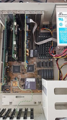
I purchased this machine - a 486 motherboard upgrade in ye olde Osborne Australia 386-SX metal case with the plastic front - back when I was doing a science degree back in the mid-90's. Had always hoped to hand it on to my kids for a healthy dose of 8-bit gaming goodness - but they are *seriously* uninterested, so am looking to move it on to a collector.

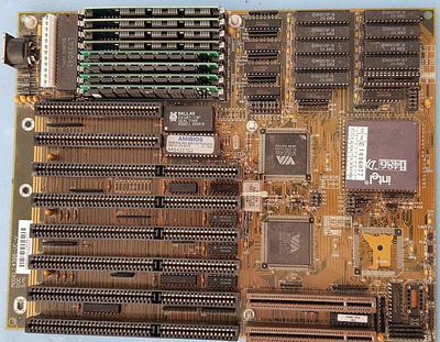
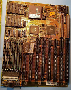
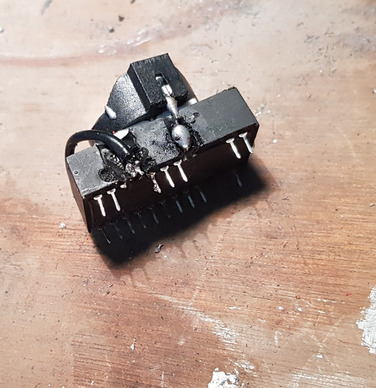
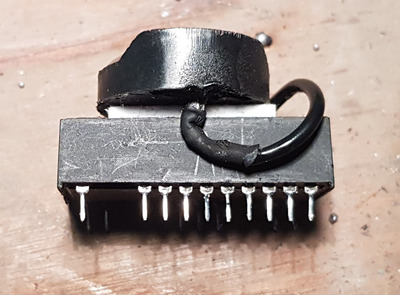
Now it had only been cranked up a few times out of storage in the last 20 yrs to make sure the 100mb HDD still had my data, but about 2 years ago it failed to boot completely for the first time - the RTC having expired. I tracked down the button-battery hack between pins 16 and 21 kindly referenced elsewhere on the Vogon forums... but found I can't actually remove the original Dallas DS1287 / 1187 RTC from the mbo. Needs a special tool I believe - or special knowledge as it doesn't actually look to me that it is socketted. I do all the "lego" side of upgrading physical components - the soldering side not so much. Is there anyone in the Brisbane area who might care to mentor me in this regard? Or has an alternative suggestion?

Cheers 😀

Reply 1 of 5, by wiretap

User metadata
Rank Oldbie
Rank
Oldbie

Regardless of the option you choose -- the cutting hack or the direct replacement, you'll need to do some soldering if the RTC is not socketed.

If you were to cut the sides of the RTC in-place, you would have to be extremely careful not to hit the motherboard. Most people use a Dremel to cut down to the traces you need to get to, but it can catch and fling the Dremel away from the intended cutting area and you'll hit the motherboard.

The safer option is to desolder the RTC from the board and either replace the RTC using a DIP socket with a new one (preferred), or you can remove the existing RTC to modify it and then reinstall (resolder) it in place.

Here's a pre-made RTC drop-in replacement with a CR2032 button cell battery.
or
Mouser carries newly manufactured DS12877+'s compatible with the DS1287: https://www.mouser.com/ProductDetail/Ma ... mlI%252B13
and
DIP socket: https://www.mouser.com/ProductDetail/?qs=dNsY … dZQyTNNzA%3D%3D

Hopefully someone local can help you out if you're not comfortable with soldering. You can also look in my signature at the link for soldering help. I uploaded the whole IPC rework manual which has step by step pictures. On YouTube, you can also look at EEVblog for great soldering tutorials in video format: https://www.youtube.com/watch?v=fYz5nIHH0iY

Last edited by Stiletto on 2020-03-02, 06:17. Edited 1 time in total.

My Github
Circuit Board Repair Manuals

Reply 2 of 5, by arobbo

User metadata
Rank Newbie
Rank
Newbie

Cheers wiretap! [edit - oops soz]
That's marvellous information for me to get started with, thank you. I can't see where there might be either a line to indicate a socket arrangement - or little holes for a pincer tool to get in - and I used as much force as I dared to try to wriggle it free - no go.
I've been brought up in a family without interest in flux stations, soldering experience or electrical hobbies etc - I feel like I've missed out 😀
Again - really appreciate your time to advise on the matter -will have to get back to this later, late here in Oz

PS finally worked out how to attach...

20200119_486_2.jpg
Filename
20200119_486_2.jpg
File size
167.95 KiB
Views
588 views
File comment
486 mobo isolated
File license
Fair use/fair dealing exception
20200119_486_1.jpg
Filename
20200119_486_1.jpg
File size
33.17 KiB
Views
588 views
File comment
486 mobo in situ
File license
Fair use/fair dealing exception
20200119_486_3.jpg
Filename
20200119_486_3.jpg
File size
175.7 KiB
Views
588 views
File comment
486 mobo rotated
File license
Fair use/fair dealing exception

Reply 3 of 5, by arobbo

User metadata
Rank Newbie
Rank
Newbie

Thanks again, wiretap for your info and cautionary advice -
I have learned the hard way that the dremel bit can have untoward consequences. Attached are snaps of a "new" Dallas RTC that I performed the hack with - but inadvertently hacked off Pin 15. My attempts to resolder a new pin (with wire from paper clip) got messier and messier, as the 2nd shot shows after I was getting too cosy with the resin 🙁
Dread to think what I would (?) do over an unprotected motherboard...

Cheers

Attachments

  • rtc fail pin 15 snap.jpg
    Filename
    rtc fail pin 15 snap.jpg
    File size
    463.66 KiB
    Views
    563 views
    File comment
    RTC mod - ugly truth of missing "tooth"
    File license
    Fair use/fair dealing exception
  • 20200119_001037.jpg
    Filename
    20200119_001037.jpg
    File size
    212.57 KiB
    Views
    563 views
    File comment
    RTC mod, sunny side up
    File license
    Fair use/fair dealing exception

Reply 4 of 5, by Horun

User metadata
Rank l33t++
Rank
l33t++

Good job ! Is that some of that Double sticky foam under the battery holder ? Good idea !

Hate posting a reply and then have to edit it because it made no sense 😁 First computer was an IBM 3270 workstation with CGA monitor. Stuff: https://archive.org/details/@horun

Reply 5 of 5, by arobbo

User metadata
Rank Newbie
Rank
Newbie

Well spotted, Horun - 'twas indeed double-sided tape! Thanks for your kind comments - literally the first play with My First Dremel. *Next time* I do something like this I would embed the pins in a protective sponge etc - the plastic packaging was too restrictive, so I went "Commando". No such commando heroics if I were to attempt the on-board modifications wiretrap warmed about - even if I were to cover the circuit-board with high-density foam matting etc during the surgery, getting the angle of the dangle for successful connection to Pins 16 and 21 would be nigh on miraculous for me. I couldn't manage the pin replacement though I have "seen it" completed on various web sites.
Work In Progress...