Oh, my mistake. I thought you had said the plug was on the PCI card, not on the motherboard next to the PCI slot. That's different.
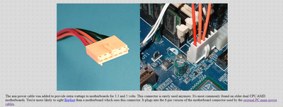
Still, be careful. The original AT and all its clones used two of those connectors, side-by-side. ATX replaced it with the 20-pin Molex Mini-Fit Jr plug. But, later, mostly for socket 423 Pentium 4s and similar era AMD CPUs, they brought back that same exact plug for additional power to the CPU -- with a different pinout, of course. It got retired pretty quickly in favor of the ATX 12V connector -- the 4-pin Molex Mini-Fit Jr plug, and then the 24-pin ATX connector, and then a 6-pin 12V connector.... Basically, the industry can't figure out how much voltage and current is enough for a CPU's main power rail, so they keep slapping new plugs all over the place -- many of which fit in the holes that other standards used. Fun! Next, let's talk about PC video connector standards....
Back on topic though... That connector could conceivably power the PCI slots (although I haven't ever seen that before -- but if it's a proprietary board, anything is possible. You have another card in the slot next to it. Does that work?
There are a few things you could do to figure this out definitively, rather than expecting some yahoos on the Internet to have the right answer:
1) Turn off the PC and unplug the PSU from the motherboard.
2) Use a multimeter in continuity mode. Stick one end on a known ground point, like one of the metal rings around the motherboard screw holes. Probe the pins on that mystery connector and see which ones beep. (I would be shocked if none are tied to a common ground. You will be shocked if you have built up a static charge.)
3) Find which pins on the main motherboard power connector are +12, +5, +3.3. See if that mystery connector is tied to any of those rails. It might be, in which case it just helps deliver more current, and can be left unplugged if you're not stressing the capabilities of the main power connector.
4) If the above test fails (no continuity to the + rails), get a pinout map of the ISA and/or PCI slots and see if their +12, +5, +3.3 pins connect to the mystery connector, or if they are in fact tied to the main power connector.
5) If you're brave, reconnect everything and power it up. Carefully probe the ISA and/or PCI slot power pins in Volts mode to make sure they're getting power.
6) Carefully probe the USB port to see if you get +5V on the connector. If not, try to trace the circuit from the USB jack back through the PCB. It'll probably connect to a polyfuse (it's often a little flat surface-mount chip, commonly green or blue) which could have burnt out. Maybe that's why they sold the card? Check the voltage on each side of it.