VOGONS


First post, by pshipkov

User metadata
Rank Oldbie
Rank
Oldbie

Attached a picture from the back of one of my Voodoo 1 cards.
I noticed that one of the elements fell off.
Cannot figure out what kind of element is this - any hints ?
Thanks.

Attachments

retro bits and bytes

Reply 1 of 17, by keenmaster486

User metadata
Rank l33t
Rank
l33t

Surface mount resistor or capacitor but there’s no way to tell what the value of it is unless you have the schematic for the card.

World's foremost 486 enjoyer.

Reply 2 of 17, by luckybob

User metadata
Rank l33t
Rank
l33t

99.9% of the time, the "L" on the silkscreen designates an inductor.

Taking a random guess, I'm willing to bet this is somewhere between the analog display output and the ramdac chip.

Unless you have a schematic, you are going to have to take an educated guess as to its value. I can help you go down that path, if you need to.

It is a mistake to think you can solve any major problems just with potatoes.

Reply 3 of 17, by pshipkov

User metadata
Rank Oldbie
Rank
Oldbie

Thanks for the feedback.
I already tried the non-scientific approach without luck.
The missing guy is at the very bottom of the picture below.
It is impossible to see where the line goes on the other side because it is under the VGA connector.

Are you aware of any Voodoo 1 schematics out there. I ran a brief search but nothing lit on the radar.

Attachments

retro bits and bytes

Reply 4 of 17, by luckybob

User metadata
Rank l33t
Rank
l33t

I looked at my v1 cards, and neither are the same, so I can't just give you a quick answer.

If I were in your position, I'd desolder L5 (important), measure its inductance, and get the closest match possible for L6.

if you dont have a proper way to measure an inductor, I'd look at one of these: https://www.ebay.com/i/372864022690 it's not perfect, but its likely to be close enough.

It is a mistake to think you can solve any major problems just with potatoes.

Reply 6 of 17, by luckybob

User metadata
Rank l33t
Rank
l33t

https://www.youtube.com/watch?v=7Br3L1B80ow

a video about it, in case you are interested.

TL;DR: Its good enough for a go/no-go or a "wtf is this part" deal. I own one and I have the lexan plastic case for it. Cost like $1 more.

It is a mistake to think you can solve any major problems just with potatoes.

Reply 7 of 17, by H3nrik V!

User metadata
Rank Oldbie
Rank
Oldbie

The "L" designators are typically inductors, agreed, but often those inductors, when that size, are more like ferrite beads used for EMI suppression, so it might prove very difficult to measure unfortunately ..

Please use the "quote" option if asking questions to what I write - it will really up the chances of me noticing 😀

Reply 8 of 17, by luckybob

User metadata
Rank l33t
Rank
l33t

true, the $7 tester might not be up to the task if it is a low-value inductor. Not really much can be done about it. Its probably for EMI or something, but its connected to what looks to be pin-15, and IIRC its for the monitor identification scheme.

have you tried using the board?

It is a mistake to think you can solve any major problems just with potatoes.

Reply 9 of 17, by pshipkov

User metadata
Rank Oldbie
Rank
Oldbie

Yes, the board used to work just fine.
Then one day i stacked bunch of hardware on top of each other while moving it around. I sensed that something fell off from the stack, but was in a rush.
After that the Voodoo stopped working. Later on, upon close inspection i noticed the missing bit.

Looked up impedance test kits. Prices are too high to justify purchase for this one-off case here.
May need to comb through ebay for cheapo donor components.

retro bits and bytes

Reply 10 of 17, by ShovelKnight

User metadata
Rank Oldbie
Rank
Oldbie

These Chinese LCR meters are quite good. I’ve tested mine (I have a slightly more expensive cased version) against PEAK Atlas and it’s surprisingly accurate, at least when measuring capacitance. What’s more important, it’s consistent in its readings.

The only problem with them is they are very easy to accidentally kill.

Reply 11 of 17, by H3nrik V!

User metadata
Rank Oldbie
Rank
Oldbie

https://www.digikey.com/product-detail/en/vis … 98-1-ND/5168395
https://www.digikey.dk/product-detail/en/mura … 92-1-ND/1016252

These are just 2 examples of that type of components. Pretty low DC resistance, but have a "tuned" frequency, where impedance is high, thus blocking high frequency emission.

I think, what I would do, was to desolder the other component and check DC resistance, maybe see if an LCR meter would give any results - and then select a component with approximately the same DC resistance .. Of course, there's a risk at this approach, and furthermore you can be sure that the board afterwards will not be compliant in terms of radio emissions 🤣

Please use the "quote" option if asking questions to what I write - it will really up the chances of me noticing 😀

Reply 12 of 17, by luckybob

User metadata
Rank l33t
Rank
l33t

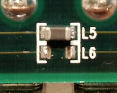
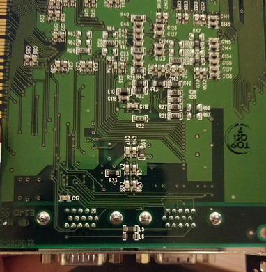
Well, looking at the traces, L5&6 seem to directly connect pins 12&15 (respectfully) to their companion connector. These 2 pins correspond to the I2C bus lines for communication between the monitor and video card. I'm relativity certain they are matching parts. In addition I also feel they aren't required for the voodoo card to function. HOWEVER they are required if you want the monitor to talk to the computer. This isnt a critical link, but it is nice creature comfort.

It might be possible to just bypass these parts. you could short L5 and L6. (not together) As long as both connections are the same, it *should* be okay. I'm not as familiar with the I2C bus as much as I'd like, but I do know serial transmission lines need to be as identical as possible.

It is a mistake to think you can solve any major problems just with potatoes.

Reply 14 of 17, by quicknick

User metadata
Rank Oldbie
Rank
Oldbie

Best approach would be to measure L5, then find an inductor of the same size and value for L6. As a temporary measure, installing a 1-10 ohm resistor in its place or even shorting L6 pads should do the trick.

Though I'm afraid the card has sustained some other damage too, as I don't see how this missing inductor would cause it not to work. Carefully inspect the board for more missing smd parts, or shorted (bent) pins on the PQFP chips.

Reply 15 of 17, by pentiumspeed

User metadata
Rank l33t
Rank
l33t

Yes that's inductor, low ohms too. Lift one from any junk video card that has same size as this around the video ports. Gets you close enough to work, even perfect.

Cheers,

Great Northern aka Canada.

Reply 16 of 17, by pshipkov

User metadata
Rank Oldbie
Rank
Oldbie

Tried early today few things.
- Shortened that line
- removed the other inductors and shortened the other line.
- swapped the existing inductors between the lines.

Win95 refuses to recognize the Voodo.
I am hesitant to take components from other boards to get two of these inductors in place.

It feels like there is a bigger problem with that card in general. Too bad.

retro bits and bytes

Reply 17 of 17, by cyclone3d

User metadata
Rank l33t++
Rank
l33t++

This thread may have actually helped me. I have a V3-3500 that had sustained some damage and I have repaired everything, including a bodge wire to go from one side of the board to the other due to a ripped off pad, but I was unable to figure out what inductor to use in in the missing one's place. Time to find one from a different dead video card and see if it will work.

Yamaha modified setupds and drivers
Yamaha XG repository
YMF7x4 Guide
Aopen AW744L II SB-LINK