VOGONS


First post, by Brickpad

User metadata
Rank Member
Rank
Member

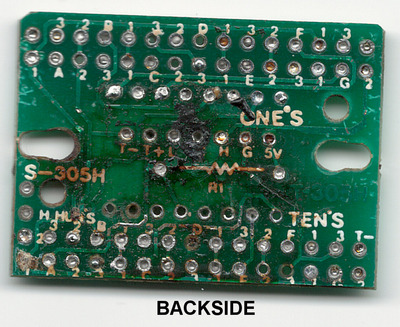
Long story short, a resistor on my S-305H display cooked its brains out and is now perma-damaged . I tried doing a repair by removing the borked resistor and bridging the two points with a piece of jumper wire, and instead adding a 22 Ohm resistor to the line going into the 5v input of the display. This sort of worked, however segment switching still didn't work properly when enabling / disabling turbo mode. My guess is that free-flowing current bridged some of the traces within the segmented display. Oh well...

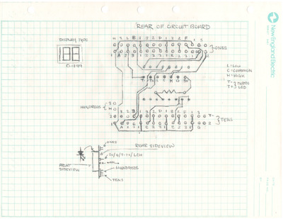
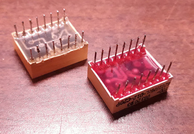
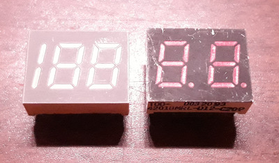
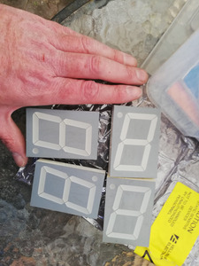
At this point I've given up hope trying to repair the display; finding another S-305H is practically impossible, so what else is there to do? Well, I've decided to take another route and dissect the board, and sketch out the trace work front and back. My thinking is this: we all know finding these MHz displays are practically impossible to find, so why not build our own? Do you think there is enough interest in having a small initial batch of custom-made PCBs? The parts themselves aren't costly - a single resistor, 34 pairs + 1 single pin pin headers, and a 16-segment display (0-199), or 14-segment display (0-99).

I will be adding more scans / sketches to this post once I've completed them.

In the meantime I would be very interested in hearing your thoughts on this?

Attachments

  • IMG_0002.jpg
    Filename
    IMG_0002.jpg
    File size
    249.74 KiB
    Views
    1303 views
    File comment
    Backside of PCB
    File license
    Public domain
  • IMG_0004.jpg
    Filename
    IMG_0004.jpg
    File size
    461.37 KiB
    Views
    1303 views
    File comment
    Backside Sketch of PCB
    File license
    Public domain

Reply 2 of 16, by H3nrik V!

User metadata
Rank Oldbie
Rank
Oldbie

Check out this thread: Fabricating a New Turbo Display

I'm not sure if it is only 2 digits, but might be good for inspiration ..

Please use the "quote" option if asking questions to what I write - it will really up the chances of me noticing 😀

Reply 3 of 16, by gdjacobs

User metadata
Rank l33t++
Rank
l33t++

Using 74LS47 jelly beans (in SMD packages if you're concerned about size) is a nice solution to lower the logic pin count and provide driver electronics in one chip. Use 74x48s if you have common cathode LEDs to go with it and you can dispense with the resistor packs. Common cathode also allows CD4511 drivers. These have latching inputs to multiplex your data lines. That would require only one extra line plus one line per digit (instead of four per digit normally) potentially allowing the use of a smaller (and cheaper microcontroller).

In most cases, we're talking <1 USD per chip. Might be worth it?

All hail the Great Capacitor Brand Finder

Reply 5 of 16, by BinaryDemon

User metadata
Rank Oldbie
Rank
Oldbie

I find it hard to believe these aren't manufactured. I'd be happy with a drive bay seven segment display that you simply pre-set and the only connection it needs would be power. I've looked to see if i can find them with each number wired to a dipswitch array but it seems every project using seven segment displays also uses an arduino.

Check out DOSBox Distro:

https://sites.google.com/site/dosboxdistro/ [*]

a lightweight Linux distro (tinycore) which boots off a usb flash drive and goes straight to DOSBox.

Make your dos retrogaming experience portable!

Reply 6 of 16, by Brickpad

User metadata
Rank Member
Rank
Member

@peg - That's the same display as mine!

I'm looking to stick with the original design of this board without having to invest time in programming and utilizing a microcontroller, or optimizing tracework. I know it's a pain to configure jumpers, but to me this would be a much simpler approach, and I'd rather just keep this as simple as possible.

Now unfortunately I don't know what the original part number was for the 2.5-digit (1xx) display as there are no markings. I was however fortunate to find a two-digit display (part# TOD-4201BMRL-B) I harvested from some type of interface a while ago that shares the exact same dimensions, including pin count, length, and size; the exception being the digits were slightly larger and are red rather than green. This is a really good score because there is an available datasheet on the TOD-4201BMRL part that has all the dimensions worked out.

All that's left for me to do is finish the schematics for the top layer, and determine if the original segment display was common anode, or common cathode.

I've attached some pictures for comparison between the two modules. On the left is the original 2.5-digit (green) display, and on the right the display from my parts bin.

Attachments

Reply 7 of 16, by gdjacobs

User metadata
Rank l33t++
Rank
l33t++

Some dual lane 0.1" strip, two large value low power resistors for pull up/pull down, one resistor for LED indicator current limit, one pnp bjt, one npn bjt, two eight pin resistor packs.

All hail the Great Capacitor Brand Finder

Reply 8 of 16, by H3nrik V!

User metadata
Rank Oldbie
Rank
Oldbie

Just hoping that I'll get to pull myself together to build one with these some day 🤣

Attachments

  • IMG_20200315_170259.jpg
    Filename
    IMG_20200315_170259.jpg
    File size
    796.55 KiB
    Views
    1107 views
    File license
    Fair use/fair dealing exception

Please use the "quote" option if asking questions to what I write - it will really up the chances of me noticing 😀

Reply 9 of 16, by Benedikt

User metadata
Rank Oldbie
Rank
Oldbie

What about a smaller three-digit module behind a rectangular piece of dark red or dark green acrylic?
That way one could match the cutout in the case and still use a readily available display module.

Reply 10 of 16, by gdjacobs

User metadata
Rank l33t++
Rank
l33t++
H3nrik V! wrote on 2020-04-09, 15:49:

Just hoping that I'll get to pull myself together to build one with these some day 🤣

For an Intel Skulltrail case, I presume?

All hail the Great Capacitor Brand Finder

Reply 11 of 16, by SETBLASTER

User metadata
Rank Member
Rank
Member

never thought this coud be possible to recreate.
i got a display that besides having 2 digits in one color. it has the words MHZ in red, i have never seen displays with words, only numbers so far and was shocked when i saw it on the case.

one of the sticks in "MHZ" is failing tho, has lower dim., after 30min of use the light kind of looks ok. perhaps we should just print something in 3d printer and just light up a led on the back.

Reply 12 of 16, by Benedikt

User metadata
Rank Oldbie
Rank
Oldbie
SETBLASTER wrote on 2020-04-10, 03:09:

never thought this coud be possible to recreate.
i got a display that besides having 2 digits in one color. it has the words MHZ in red, i have never seen displays with words, only numbers so far and was shocked when i saw it on the case.

one of the sticks in "MHZ" is failing tho, has lower dim., after 30min of use the light kind of looks ok. perhaps we should just print something in 3d printer and just light up a led on the back.

... Or you could just use a 2D printer:

  1. Create a custom PCB for the desired LED layout
  2. Populate it with LEDs
  3. Print a mirror image of the inverted (i.e. white on black) layout on thin paper
  4. Put it behind acrylic with the printed side facing the LEDs

Reply 13 of 16, by imi

User metadata
Rank l33t
Rank
l33t
SETBLASTER wrote on 2020-04-10, 03:09:

never thought this coud be possible to recreate.
i got a display that besides having 2 digits in one color. it has the words MHZ in red, i have never seen displays with words, only numbers so far and was shocked when i saw it on the case.

just look for an alphanumeric LED to display letters, you can still buy those new, might be difficult to find one that fits exactly though.

Reply 14 of 16, by H3nrik V!

User metadata
Rank Oldbie
Rank
Oldbie
gdjacobs wrote on 2020-04-09, 23:50:
H3nrik V! wrote on 2020-04-09, 15:49:

Just hoping that I'll get to pull myself together to build one with these some day 🤣

For an Intel Skulltrail case, I presume?

Haven't measured, but probably just in a 5.25" bezel if it fits ..

Please use the "quote" option if asking questions to what I write - it will really up the chances of me noticing 😀

Reply 15 of 16, by gdjacobs

User metadata
Rank l33t++
Rank
l33t++
H3nrik V! wrote on 2020-04-10, 13:54:

Haven't measured, but probably just in a 5.25" bezel if it fits ..

How mundane. I'll let you know if I see a spare Jumbotron around.

All hail the Great Capacitor Brand Finder

Reply 16 of 16, by Socket3

User metadata
Rank Oldbie
Rank
Oldbie
Brickpad wrote on 2020-04-08, 02:52:

@peg - That's the same display as mine!

I'm looking to stick with the original design of this board without having to invest time in programming and utilizing a microcontroller

I second this. Not everybody has the gear and knowledge to program a microelectronic, and price is a factor as well. The simpler and cheaper the better. The only change I would make is replacing the jumper bock with dip switches.